Ever since we learned of solidThinking, way back when, the computer-aided industrial design (CAID) tool has intrigued us as a possible architectural conceptual modeler application. Why?
Well, for starters there are not a lot of Mac-native advanced surface modeling applications in existence and most of the best tools for industrial and product design have traditionally been on Windows. Sure, there are some noteworthy exceptions on the Mac. I can hear readers saying, “well, what about this, what about that?”
And you are right.
This isn’t a product review, so in all fairness we should mention some of the most noteworthy exceptions. These would definitely include the near legendary formZ from AutoDesSys, Inc., and the equally venerable Ashlar-Vellum family of products–all of which were born on the Mac, no less. But solidThinking came later to the Mac OS platform…and, as such, many Mac designers and architects are not yet familiar with this application.
The second reason why solidThinking might be interesting for architectural modeling is because it has some unique abilities. solidThinking Evolve provides a super tight and efficient environment that combines powerful yet approachable organic surfacing, construction history and integrated rendering. It’s this particular combination of these three features–with some of solidThinking’s special abilities–that caught our eyes years ago and had us thinking about the tool for advanced architectural forms.
Frank Gehry Like Surfaces
One of the cool features we noticed early with this program–a program that is purpose built for designing things like cool bicycle helmets–is how easy it is to manipulate a few basic parameters and quickly iterate a dozen or so times within a few minutes. Additionally, we also noticed several releases back that the program came with these glossy, metallic surface shaders which made for visually interesting architectural forms. The kind of work Frank Gehry has become world famous for.
The latest version of solidThinking Evolve 2014 just was released in late February. As noted before this isn’t a product review. We will hopefully do a complete product review of Evolve 2014 in the months ahead. The purpose of this feature article is to demonstrate and explain how a NURBS-based surfaced modeling tool, one oriented at the product design space–can be used for architectural concept modeling.
Early Steps – Curved Object Basics
Using solidThinking Evolve for conceptual architectural modeling assumes something. Namely, it means you are interested in complex surfaces in architectural design. This means more than just circular-based domes and vaults…or drums or walls on radii.
However, to start out you actually may begin with such shapes, as in the example we will lead with below. In this case we are going to start with a sphere. (see image 01). Now for those who maybe wondering, before doing conceptual architectural surfaces modeling work in Evolve, they may want to set their units in the preferences to something larger in scale. The default setting, if memory serves, is centimeters. solidThinking doesn’t do feet and inches together like traditional architectural tools like say SketchUp, formZ or a BIM program. If you choose feet you will need to work in decimals of feet for your inches work.
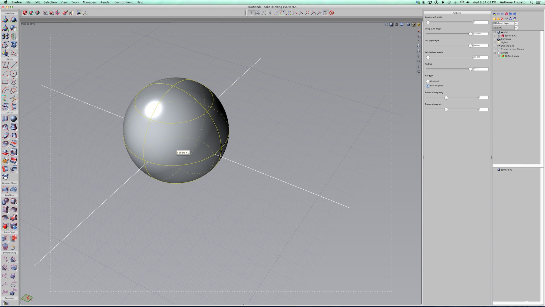
01 – the solidThinking Evolve interface with a sphere chosen. The UI is traditional in that there are tools on the left, organized in a traditional two-col. format, with inspector, layer, construction tree and scene management palette zones on the right of the main viewports.
For our work we chose meters as our unit and for most architects or architectural design professionals working in most places beyond the US metric units like meters would work well.
What we have in front of us above is a 90 meter wide sphere. And we are going to play with its shape using some of the most straight-forward tools in Evolve. This will serve as an introduction to the basic methods of the program. In solidThinking Evolve we can choose from a variety of primitives which have various parametric controls. For a sphere, the parametric controls consist of its radius, top and bottom latitude angles and a few more. Let’s review three levels of editing the sphere in the images below.
There are three object selection button icons on the top left. (see image 02) The first one is for single-clicking, selecting an object. It will pre-select highlight in dashed yellow lines (everything in the UI is customizable so this color could be changed) and once selected shows in solid yellow lines. Object parameters can be edited in the object inspector palettes on the right (see image 03) where items like radius, in this case, and latitude and longitude start and end angles can be adjusted to create various alterations to the basic sphere. (see image 04)
02 – Single click selection of a cube. Three selection modes shown in three left most icons.
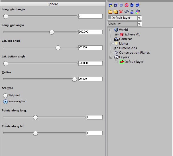
03 – Objects can be parametrically edited across a range of parameters.
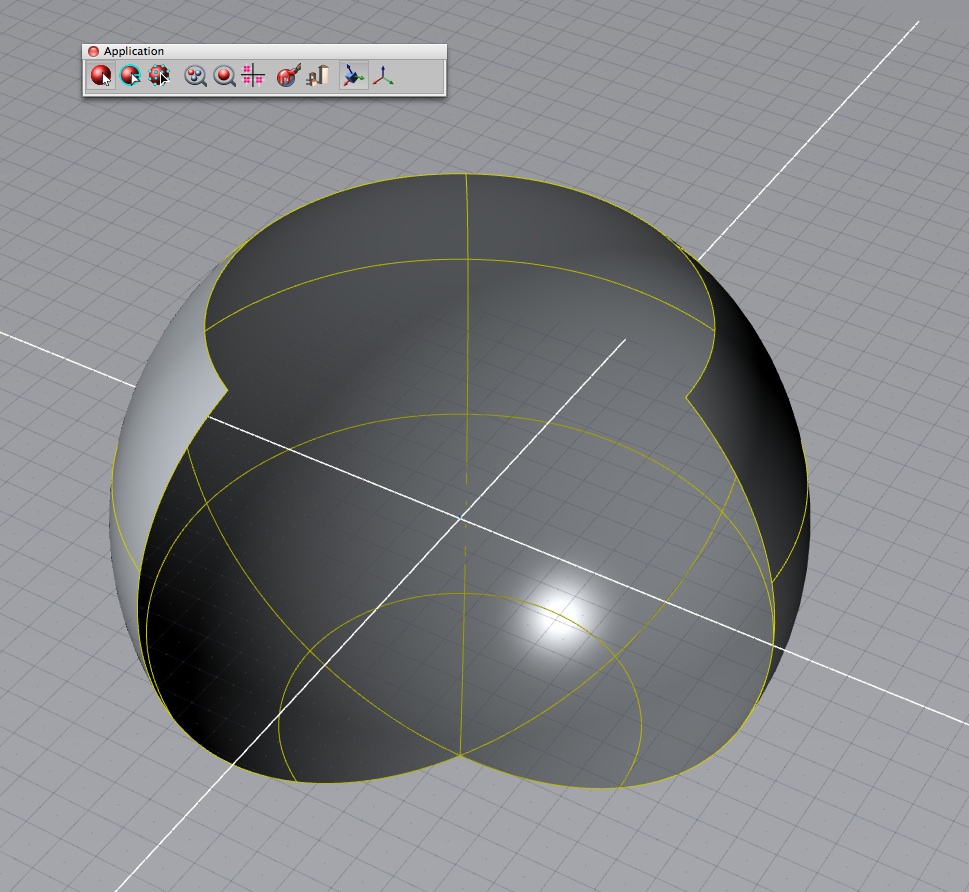
04 – This sphere has been edited across several of its parameters, including top latitude angle and longitude start angle.
We have explored the left most selection icon and the second most left selection icon. That second icon is called the Select Parameters button. Double click an object to enter this mode or use this tool button. Parameters of an object are displayed in light blue and can be selected by the mouse and dragged to enter or change values. Or you can enter values into the palette or use the sliders. (see image 05)
The third button is called the Editing Points tool button. With this button you can edit individual points along hull lines, shown in green. Hull lines are a convenient way to select all of the control points that lie along an object’s isoparm. If you are wondering what an isoparm is we can explain. (see image 06)

05 – In object parameter edit mode the “parameters” of an object are highlighted in light blue. You can select them and drag on them to edit values or control those values in sliders or a text box within the right palette.
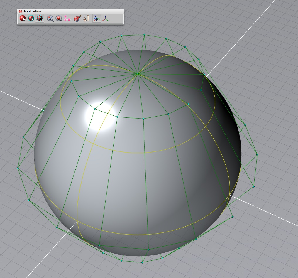
06 – In object edit points mode green hull lines array control points that lie on an object’s isoparm. You can individually select single or multiple control points and edit their location in space to dramatically change the nature of forms.
The word “isoparm” is short for “iso-parameter” which itself is referring to the way a surface is calculated. Iso comes from the Greek isos, which means equal. So think of the statement parameter equals and thus “isoparm” defines the characteristics of simple and complex surfaces.
Next page: Working in Points Mode and Shaping a Complex Roof

Reader Comments
Julia Garden liked this on Facebook.
Peeradon Warithkorasuth liked this on Facebook.
#CAD solidThinking Evolve for Architectural Design Modeling Part 1 http://t.co/vbWwbCX06E
#CAD solidThinking Evolve for Architectural Design Modeling Part 1 http://t.co/vbWwbCX06E
Julia Garden liked this on Facebook.
Julia Garden liked this on Facebook.
Peeradon Warithkorasuth liked this on Facebook.
Want to design a sexy skinned high-rise? Check out this solidThinking article on architectural design.
Want to design a sexy skinned high-rise? Check out this solidThinking article on architectural design.
Comments are closed.