COMPUTATIONAL DESIGN WITH BENTLEY’S OpenBuildings Designer is enabling JPW (Johnson Pilton Walker) to completely shift the way their studio thinks about practice—allowing them to spend more time on design and solving problems and much less time on representing and documenting those solutions.
Large and marque firms are using AAD (algorithms-aided design) or, often called, “computational design,” but many are also missing out on understanding how to formulate ways to script tools that aid production and address quality control concerns like JPW have tackled.
Such efforts recently won the firm a nod as a finalist in the global 2019 Bentley Infrastructure Awards in the Buildings and Campuses category, for their excellent work with computational design at 6 & 8 Parramatta Square.
Our teams are actually smaller than they used to be. The team started quite small, about six people. In the past, there would have been a team of about twenty.
JPW has been involved with the Parramatta urban renewal efforts since the masterplan days and has won successive competitions for multiple buildings. The first projects, known as 3 Parramatta Square and 4 Parramatta Square, were large but smaller than 6 & 8 Parramatta Square—with the latter being the primary exemplar of the use of AAD using Bentley’s OpenBuildings Designer GenerativeComponents (OBD-GC).
This particular project, 6 & 8 Parramatta Square, will actually be the largest building in Australia, once complete, with a total of 130,000 square meters of area. At 55 stories in height, 8 Parramatta Square, with its unique silhouette, will mark the district in the broader Sydney skyline and form the centerpiece at the heart of the urban renewal project. It sits adjacent to and integrates with Parramatta Station.

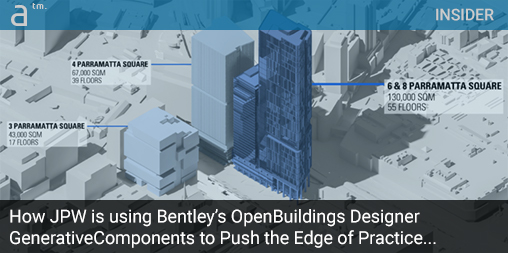
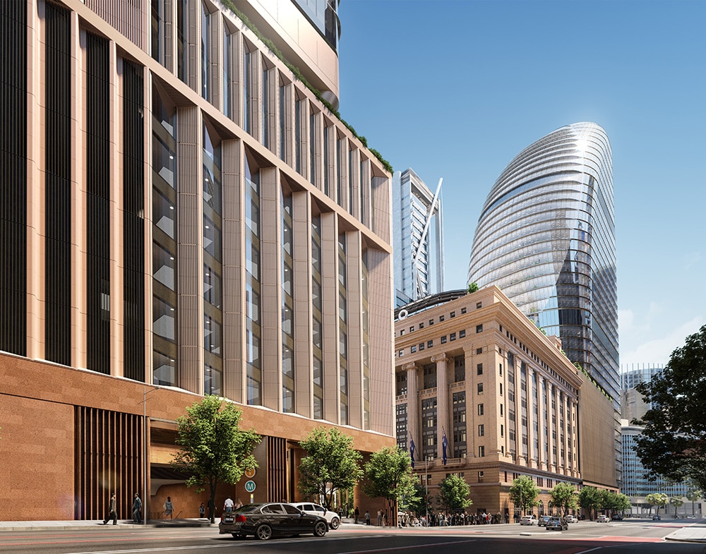
A street-level rendered view of 6 & 8 Parramatta Square, designed by award-winning Australian architecture firm Johnson Pilton Walker (JPW). The project was a finalist in the 2019 Bentley YII Awards in the Buildings and Campuses category. (image: JPW / Architosh. All rights reserved.)
What is remarkable about JPW’s work through the Parramatta Square projects is the firm’s evolution in the development of new processes and workflow efficiencies by tapping the power of Bentley’s OpenBuildings Designer GenerativeComponents (OBD-GC). This has been driven, partly, by faster project schedules. Design and documentation of 6 & 8 Parramatta Square are scheduled for three and a half years, while 4 Parramatta Square will take five.
“Our teams are actually smaller than they used to be,” says Wayne Dickerson, principal at JPW. “The team started quite small, about six people,” says Wayne. “In the past, there would have been a team of about twenty.” With smaller teams and a faster pace for what are much larger buildings for 6 & 8 Parramatta Square, JPW had to look at adopting new design approaches to gain efficiencies.
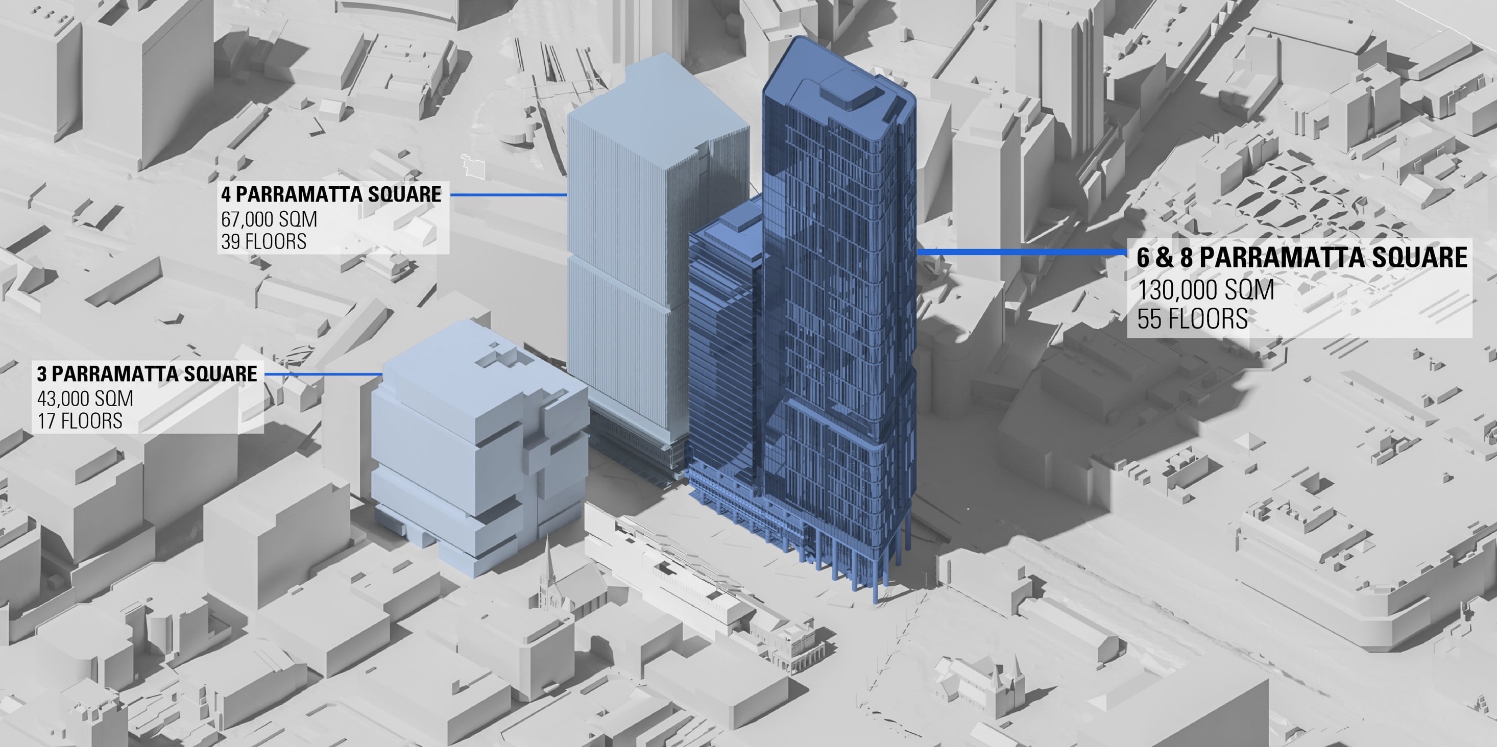
JPW has been involved in the Parramatta Square development area since master planning. 8 Parramatta Square is the tallest structure and demands a significant silhouette in the skyline. (image: JPW / Architosh. All rights reserved.)
They began evaluating where computational design methods presented advantages. Bespoke areas of the project, like the basement, podium, and core were conventionally BIM-modeled in Bentley’s OpenBuildings Designer, while areas that were generated by consistent geometric principles, such as the tower structure, tower facade, and ceilings, were scripted with GenerativeComponents technology in OpenBuildings Designer.
“Architects often design to their own intuitive logic,” says Sarah Yap, JPW’s computational design expert on the project. “Computational design is about making that logic explicit, teaching the computer to think in ways we do.”
Computational Design and the Structural Model
When JPW integrated AAD (algorithms-aided design) technologies into the project, much of the conceptional design work had already been resolved. “Typically, computational design would be integrated into the project at the concept stage,” says Sarah. “There were still huge efficiencies to be gained by introducing computational design later in the design process.”

The parts of the building modeled via conventional BIM modeling.
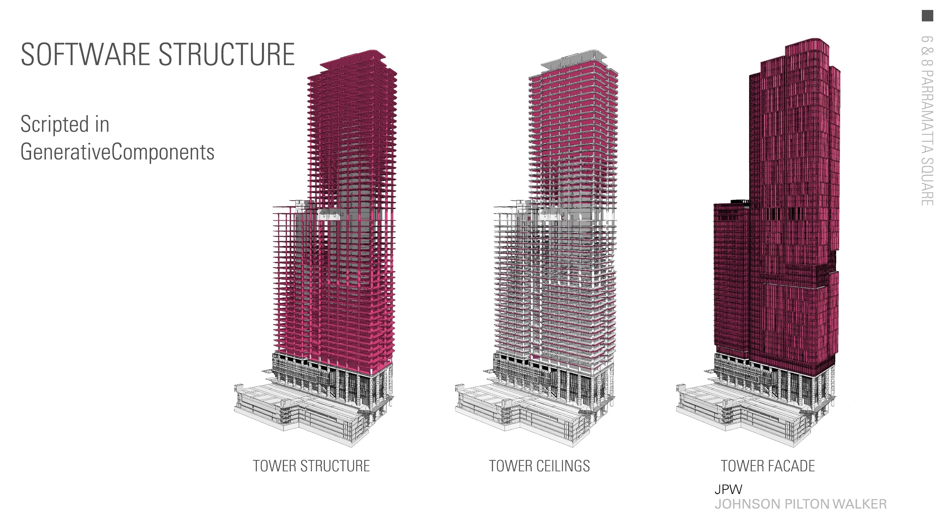
The parts of the building modeled via computational design.
Contractually, JPW was responsible for providing an architectural, structural model that is used for the coordination of services and to verify the model from the structural engineer. The structural engineers sent over tabular data on columns, beams, and slab thicknesses; engineers like to see numbers to verify their calculations, but architects want to see orthogonal drawings to help them understand the spatial implications of the design.
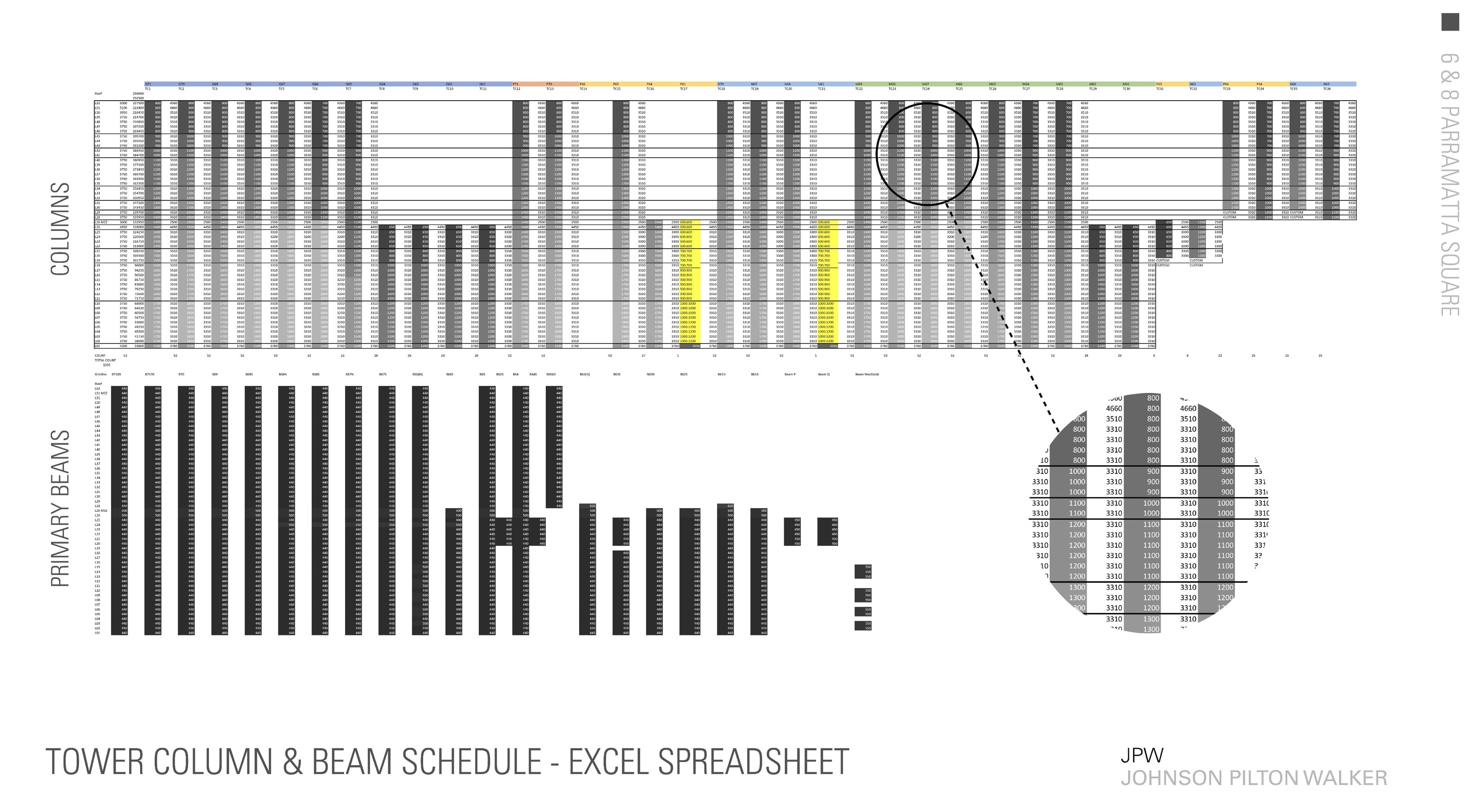
JPW utilized Excel tables to coordinate structural engineer consultant data and to load, check, and generate computational design models for structure. In other words, the Bentley computational design model could be driven by an Excel spreadsheet and thus enabled both coordination and model generation to be handled from this spreadsheet. Color-coding in Excel cells aided checking and coordination work. (image: JPW / Architosh. All rights reserved.)
To better resolve these differences between the engineers’ and the architects’ workflows, JPW used Bentley’s OpenBuildings Designer GenerativeComponents (OBD-GC) capability with Excel to customize an accelerated and semi-automated workflow for both generative and coordinative purposes. “In order to coordinate our structure, we wanted to compare a table against another table, like with like data,” says Sarah. So the JPW team created their own Excel tables where each cell contains data relating to either the diameter or the height of the column. Excel’s conditional cell formatting changes the colors in the columns in the table, so it is visually apparent where the columns change size as they rise through the tower. A similar table was created for the depths of beams and directly tied to the columns; when one value changes—like the depth of a beam—so too will the height of the column.
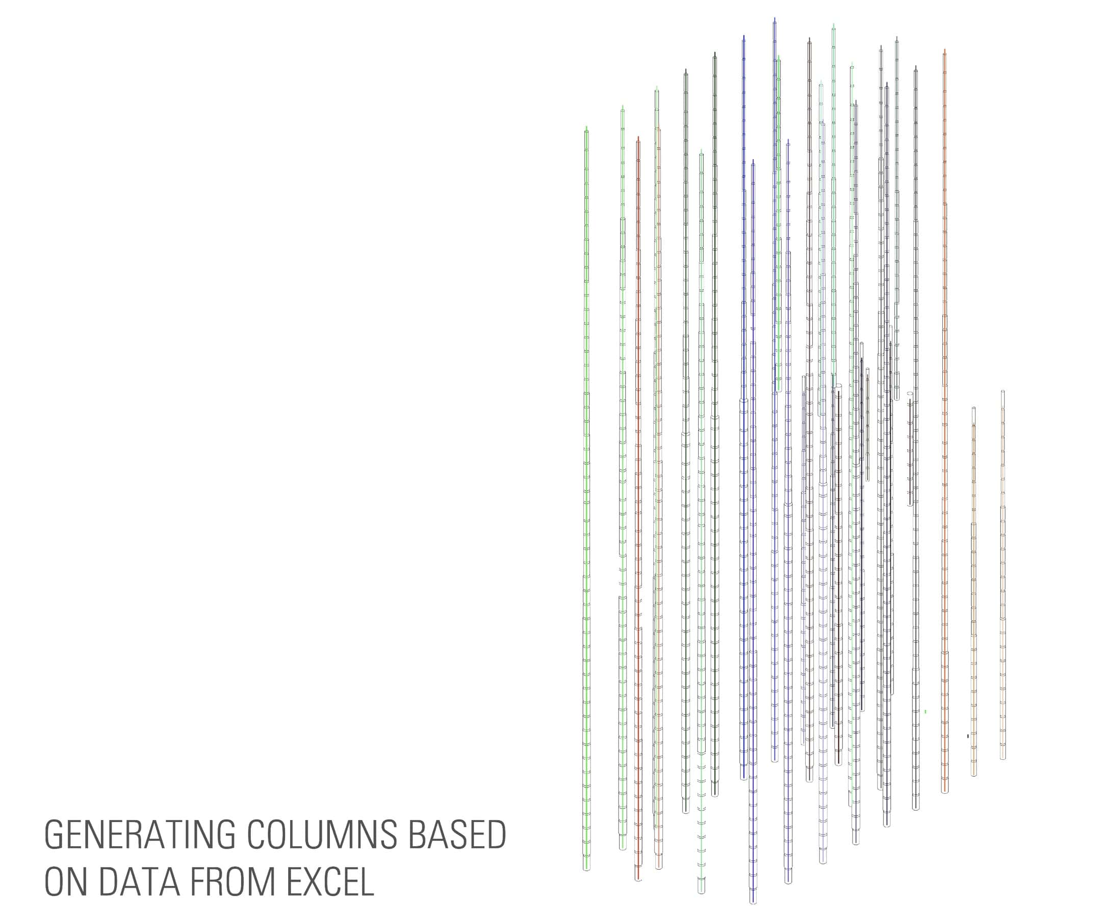
Generation of structural columns from Excel data via OBD-GC. (image: JPW / Architosh. All rights reserved.)
All of this Excel data then gets utilized in OpenBuildings Designer GenerativeComponents (OBD-GC) and is pulled from the tables, such as column height and diameter data, to generate the columns in OpenBuildings Designer GenerativeComponents. A similar process generated the beams. The slabs, however, were handled exclusively through scripts in OpenBuildings Designer GenerativeComponents (OBD-GC) and collectively, scripts automatically color-code 3D elements in the model based on parameters.
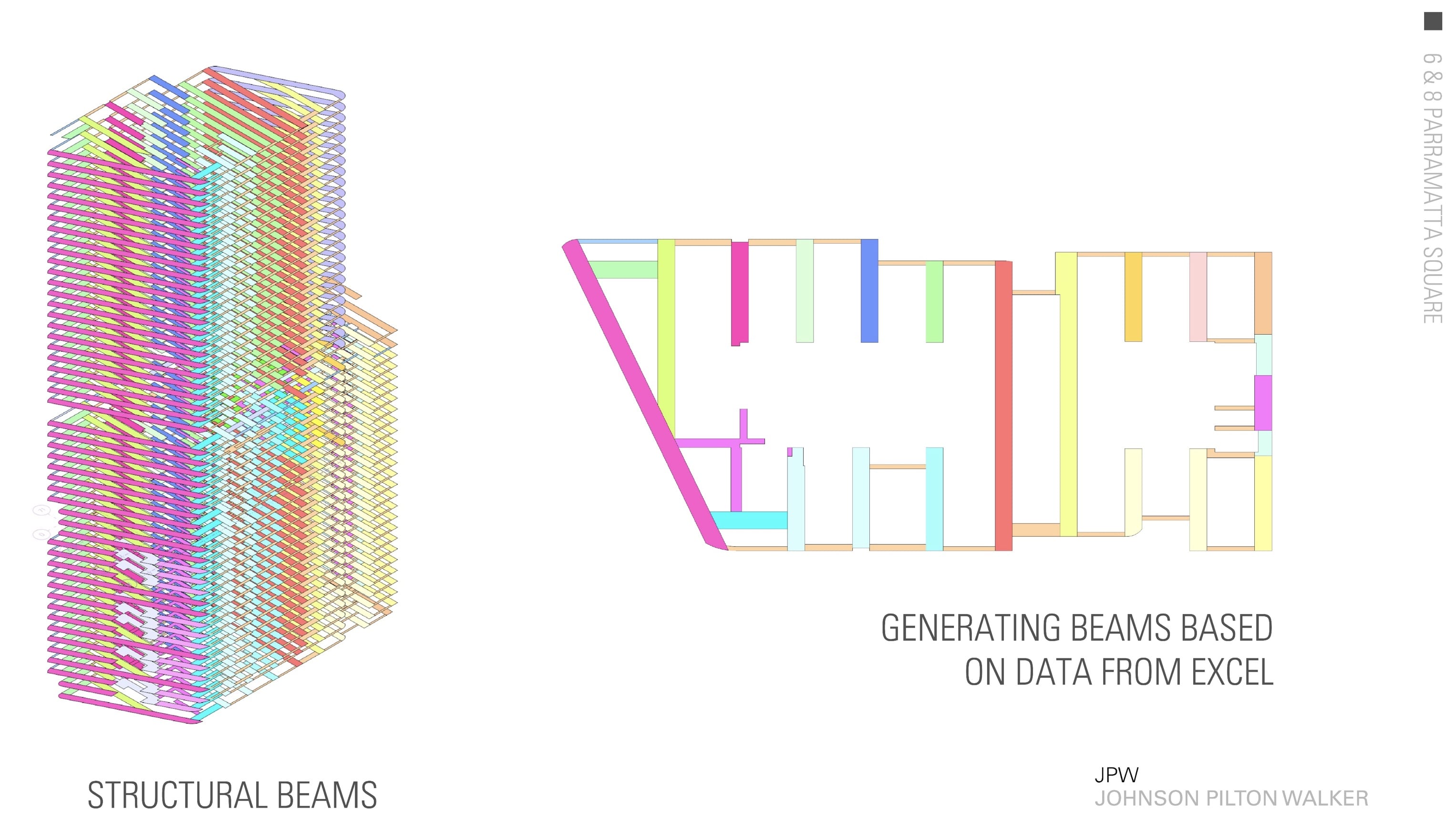
Conditional formatting in Excel carries over to (OBD-GC) scripts enabling color to aid the process of visually checking the model. Beams are generated here via (OBD-GC) scripts from Excel data. (image: JPW / Architosh. All rights reserved.)
With the architect’s structural model—the responsible instrument of service for coordination and final determinate layout in the field—JPW developed more precise methods of coordination, then simply manually selecting elements in a BIM model to confirm data.
“In a BIM program, you can select an object, and you get all this information on the panel on the side,” says Sarah, “but a lot of times, all that information really isn’t necessary. All I really care about at that moment is: what is the thickness of that slab?” Wayne said the color-coding gives you an immediate capacity to visually check the model.
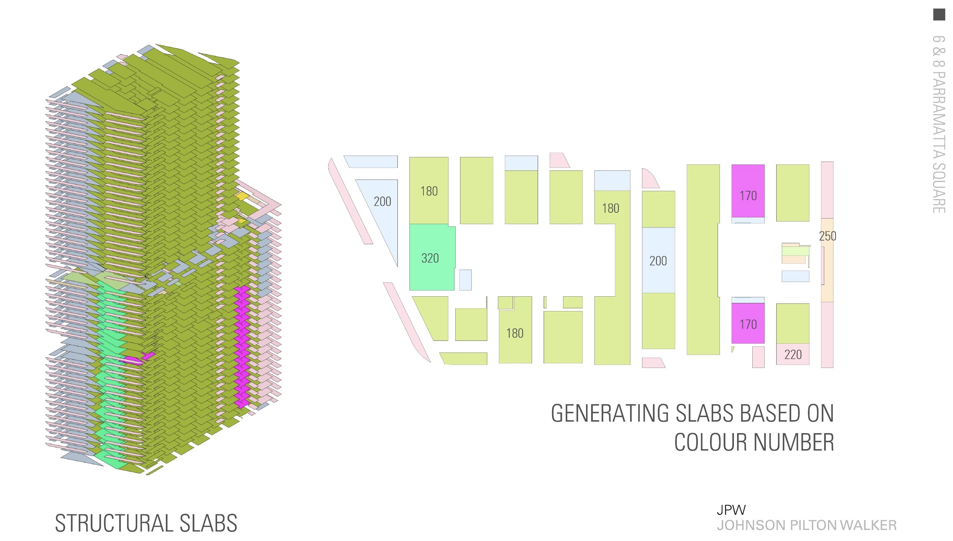
While slabs were not generated via Excel data, the same conditional color-coding was scripted in OpenBuildings Generative Components (OBD-GC) for floor-slab generation. (image: JPW / Architosh. All rights reserved.)
With the concrete structural model now generated, JPW next created a recursive script in OpenBuildings Designer GenerativeComponents that would export each of the floors, level by level, traveling up the tower, after each floor has services penetrations subtracted from it. This process required the solid modeling slab penetrations, which were used in Boolean operations as part of the subtraction from the slabs.

A recursive script punches out the holes for services chases, which are modeled as solids in (OBD-GC) and then exports finished floor slabs to Bentley’s OpenBuildings Designer. (image: JPW / Architosh. All rights reserved.)
In my discussions with Wayne and Sarah, I asked why it wouldn’t be just easier to obtain an IFC model from the structural engineer. Their answer was three-fold. Contractually, they can’t simply reuse the engineer’s structural BIM model even if they had created one. The other was the quality issues with IFC. “Getting the structural data through an Excel file would actually be a lot cleaner for us for use with GenerativeComponents,” says Wayne, “a lot of times we get very good IFC models but other times we don’t.”
“The third and most important reason is that as architects it’s important that we understand the spatial implications of the structure,” adds Sarah, “and often modeling is the best way of familiarizing ourselves with the spatiality of three-dimensional objects but also the numerical data associated with them.”
Computational Design and the Facade System
8 Parramatta Square’s facade design needed to be striking. As the signature commercial tower in the master-planned development, the design team required iterative flexibility to achieve their goals of creating a sophisticated facade using multiple variations within a curtain wall system of metal and glass.
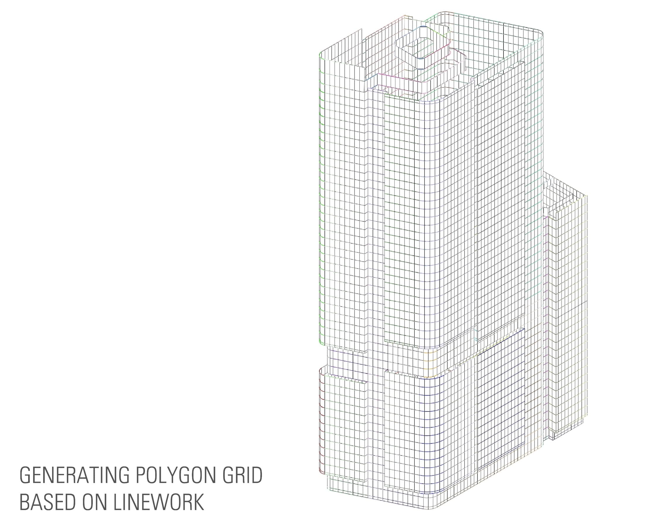
Facades are ideal for computational design, yet JPW’s team also used Excel creatively to both serve as data input and design device. Above, we see a polygonal grid generated by OpenBuildings Designer GenerativeComponents (OBD-GC) with each polygon corresponding to a “cell” in an Excel spreadsheet. (image: JPW / Architosh. All rights reserved.)
JPW’s approach was to utilize a script that established a polygonal grid, the envelope encompassing the building, where each polygon represented a panel in the facade system. They then created an Excel spreadsheet that tied back to the GC scripts controlling the polygonal grid. The Excel table was, in essence, says Sarah, “an unrolled diagrammatic elevation.”
It took me a week to do the first one. Then I could just take the script and modify it for the second one, which took me a day. And the next one took me an hour.
Each of the panels was parametric on multiple levels. “We could easily modify the dimensions of the various elements of the panels,” says Sarah. “This was critical because of the depths of the panels; their radii were constantly changing due to the demands of the client and the council.”
It turns out the panels were a typology of parts, varying dimensions of elements and omissions or additions of elements. These panel types were not modeled traditionally but generated via scripting. “It was actually how I learned the GC software,” says Sarah, who studied McNeel’s Grasshopper at university. “It took me a week to do the first one. Then I could just take the script and modify it for the second one, which took me a day. And the next one took me an hour.” That is a very accelerated learning curve and speaks to the power of iteration and automation through algorithms.
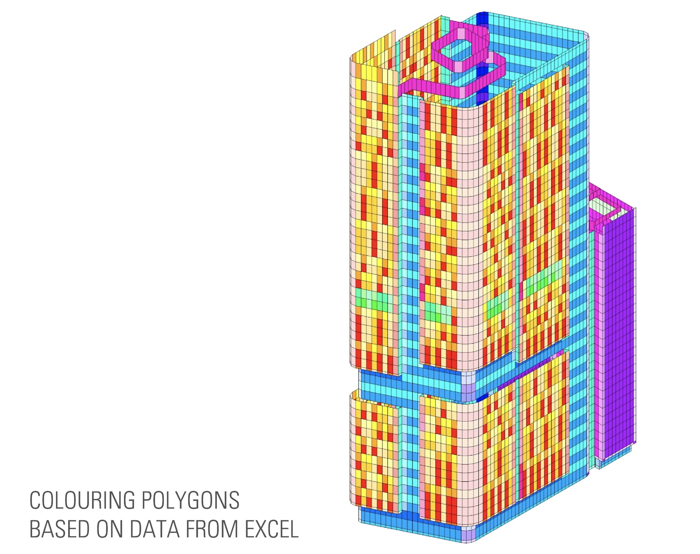
A view of the GC facade model with each polygon with matching color-coding from the Excel table. The unique colors correspond to a unique value in the table, which in turn places a complete facade panel into that polygon. See other images. (image: JPW / Architosh. All rights reserved.)
Like the concrete structural model, again, we see the creative use of Excel in conjunction with OpenBuildings Design GenerativeComponents.
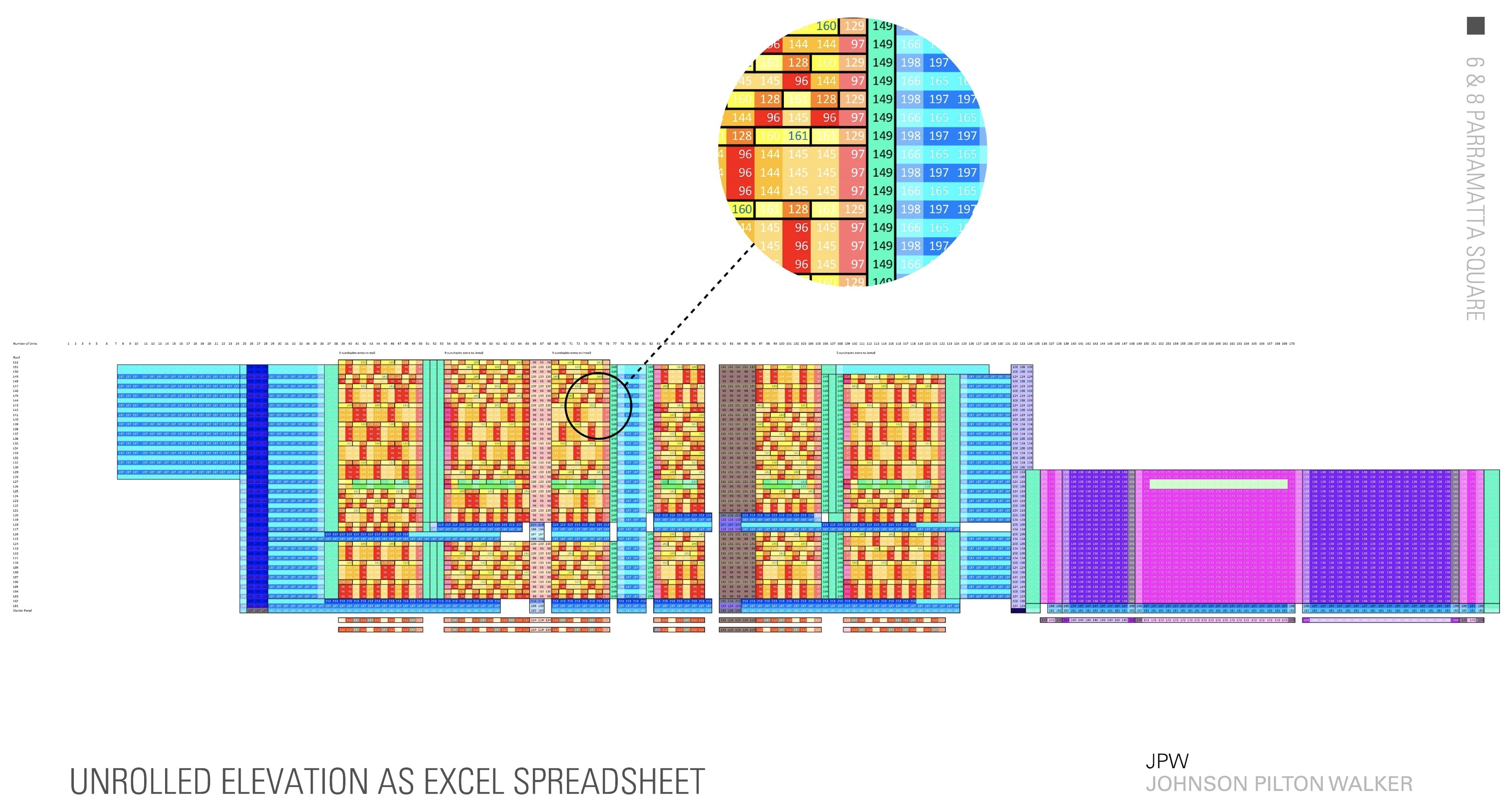
An image of the Excel table as a type of “unrolled facade” that allows designers—especially those with no computational design skills—to interact with the design. By inputting various numbers, colors change in the cell, confirming a particular architectural panel expression. (image: JPW / Architosh. All rights reserved.)
Wayne expressed an interest in how the Excel data could be approached in collaboration with other principals in the firm. “The query was, how can we take that envelope Excel drawing and actually markup the facade? How can we markup that data and then quickly take it back into Excel?” His comments point to the fact that older architects are very unlikely ever to use visual scripting tools, but many use Excel, and they also sketch by hand—it touches on the issue of how to translate a traditional analog method of design into the digital realm.

A script in OpenBuildings Designer GenerativeComponents generated unique facade panel types. They are then wired into the master facade script to essentially auto-generate facade modeling one panel (polygonal cell) at a time across the facade. (image: JPW / Architosh. All rights reserved.)
The intriguing “feature” possibility here is a kind of Excel-like table in OpenBuildings Designer or another tool that can be both printed and interacted with at the “data level” quite simply—pushing its cell data back into scripts powering the model and serving up the iterative needs of the design.
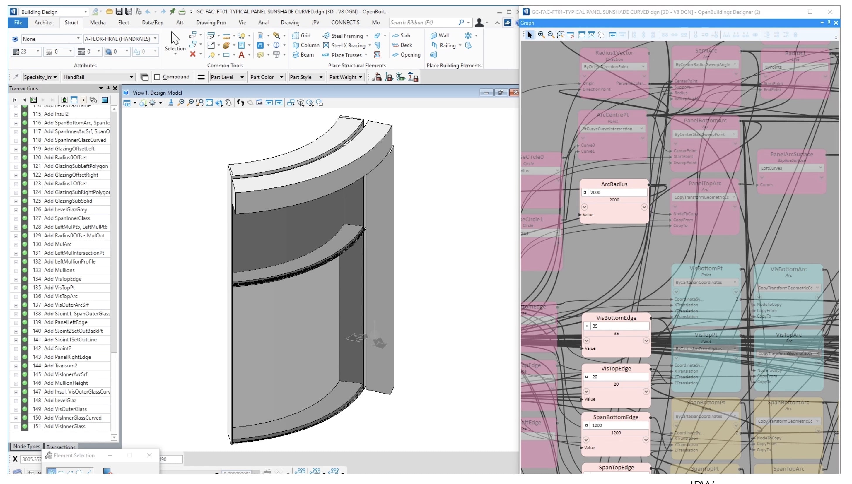
A view of the OpenBuildings Designer GenerativeComponents scripts for panelization optionality. A unique script generates a unique panel and is wired by number to the master script, which in turn obtains its number by the Excel table. Thus to model different overall facade expressions one changes numbers in the Excel table. (image: JPW / Architosh. All rights reserved.)
While AAD (algorithms-aided design) is most often applied to facade design the parametric typology of panels in combination with the use of Excel data tied into scripts gave JPW two layers of design interaction. A simple number change on the Excel table inserted a different panel type, while scripts parametrically controlled panel type attributes, like extrusion depths, fins, and other attributes. With both the client and the council suggesting changes, this rapid way of responding saved countless hours compared to typical BIM modeling alterations.
GC and Ceilings
With JPW contractually obligated to deliver a BIM model to LOD300, it meant they were required to model many details and fittings architecturally. Recognizing that ceilings are generally driven by other parts of the building, it seemed possible to use OBD-GC to create a script that could automate this 3D model process, similarly to how the structural slabs were generated.
“Typically modeling a ceiling to this level of detail would be near impossible,” says Sarah, “and it is something that our practice has never attempted. GenerativeComponents has made it realistic for us to fulfill this contractual requirement from the general contractor.”
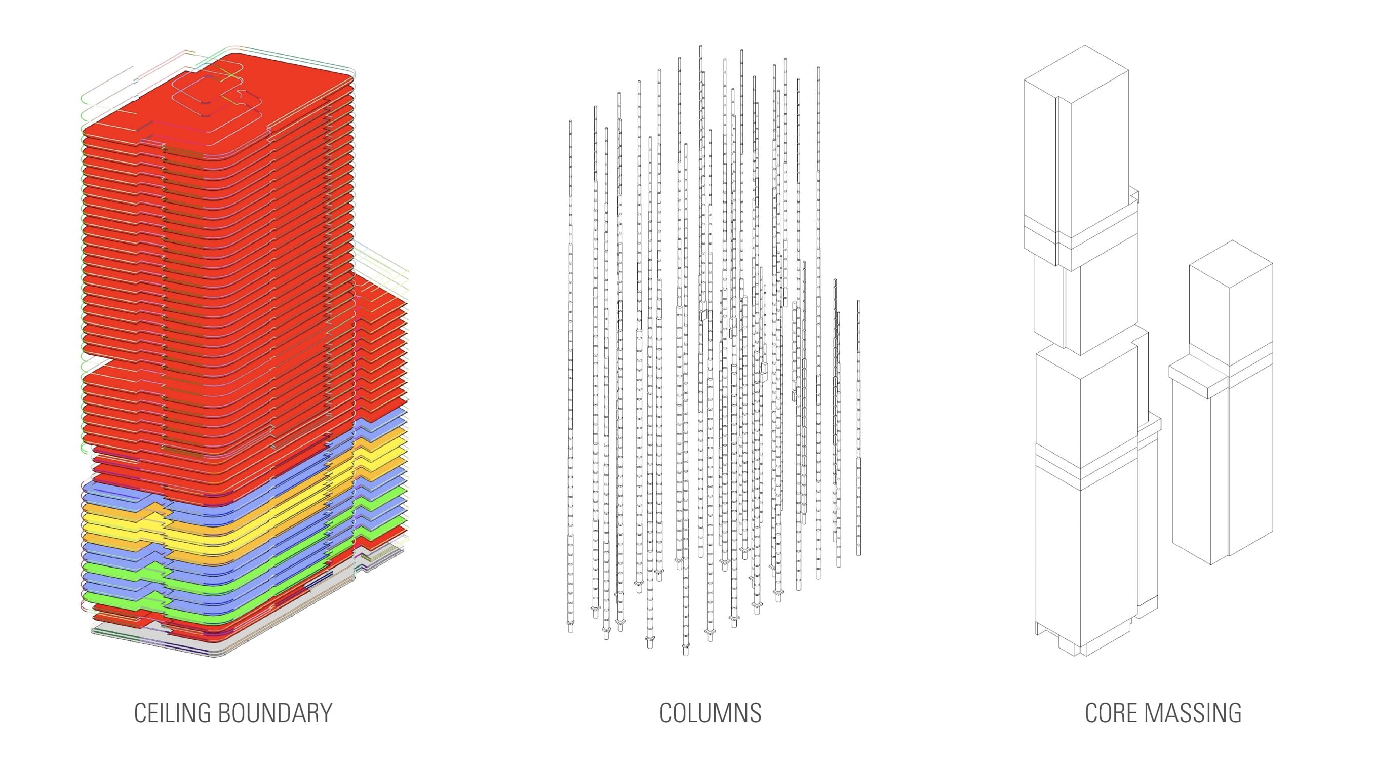
Bentley OBD-GC scripts have similarly been applied to modeling the ceilings. Data for the scripts were derived from ceiling boundary, columns, and core massing. (image: JPW / Architosh. All rights reserved.)
Their script starts with the outline of the building, offset from the facade, and then references in columns and core massing. All this gets subtracted from the “ceiling region” as defined in the script. Then the region is sliced into thousands of tiles based on a variable setup point and the tile dimension selected by the contractor.
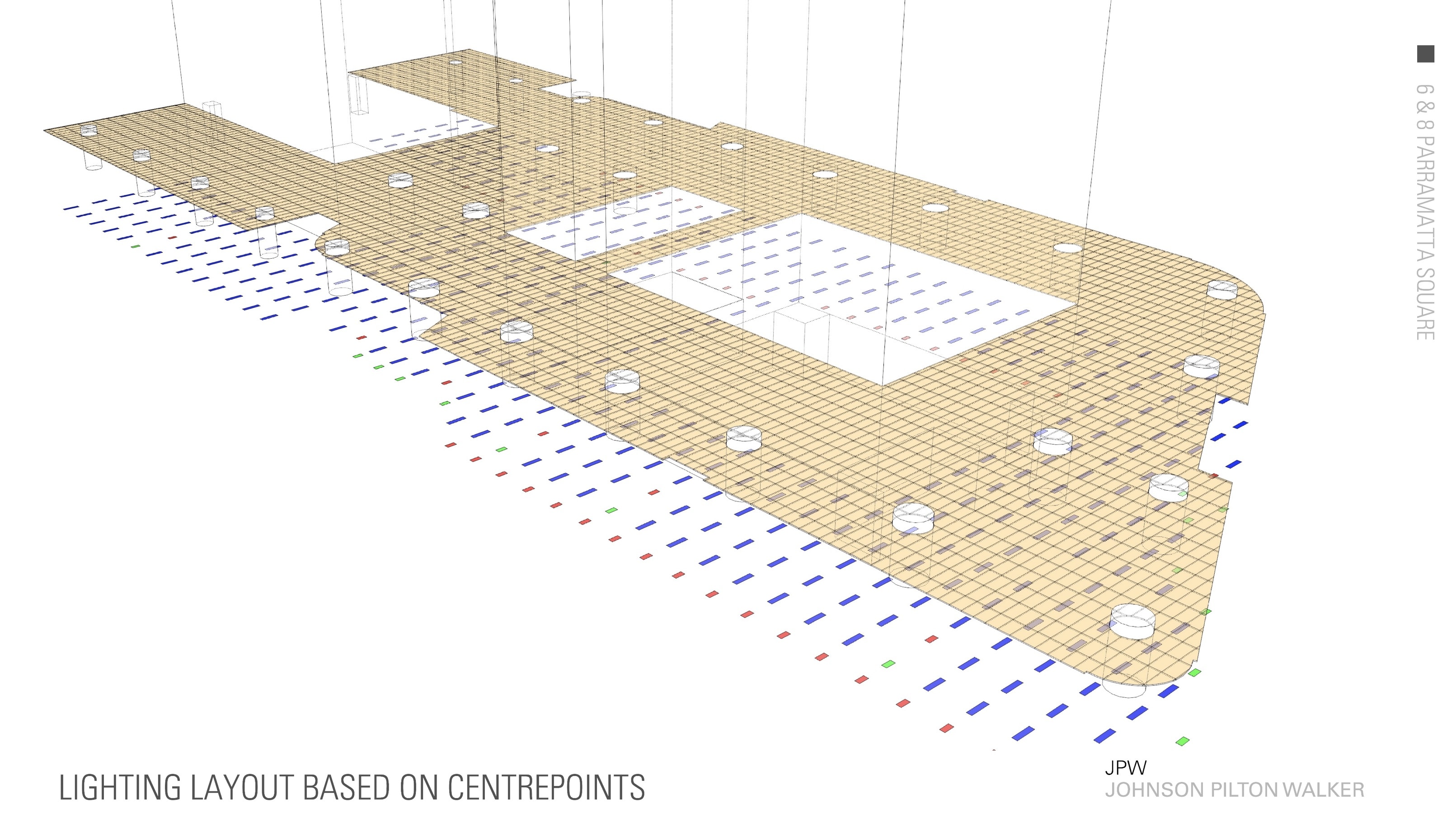
The OBD-GC scripts utilized Excel in that data from overlapping coordinate systems between the ceiling grid and lighting layout cross-checked and performed functions in Excel prior to subtractions of panels in the ceiling grid model. (image: JPW / Architosh. All rights reserved.)
The ceiling lighting layout is then referenced in using a system of color-coded rectangles to relate to different lighting types and sizes. The center points of the color-coded rectangles are then exported to Excel, with cells containing the X, Y, and Z coordinates of light fixture center points. Those numbers are then cross-referenced against the tile center points, and if these coordinates match within a certain tolerance a tile is replaced with a light cell.
A similar process was used for the layout of the HVAC ceiling diffusers, by referencing in an IFC model of the engineer’s ductwork and using a bounding box to derive a center point and then coordinating matches to have scripts cut out a precise hole for the diffuser.
Future Lessons—AAD Limitations
In review, JPW took on three major areas of the design, documentation, and coordination of 8 Parramatta Square and found novel ways to combine AAD into the firm’s evolving studio processes. In both the first and third cases, where coordination was crucial, JPW told us that it was the general contractor’s contractual obligation to perform clash detection. However, to streamline coordination between the trades JPW also performs its own in-house clash detection.
However, the firm notes that beyond clash detection there are so many other ways a model can be wrong. Using Bentley’s OpenBuildings Designer GenerativeComponents (OBD-GC) technologies the firm has addressed this challenge in scripts. The first way was in using color-coding to establish visual differentiation. Bold colors were used to create immediate recognition and establish visual patterns that would likely correspond to other patterns in the structure. This was done at both the OBD-GC script level and the Excel level.
Secondly, Sarah says they are scripting failure mechanisms into the data flow, so that if input data doesn’t match output data then in some cases the script will fail. This process reflects the software world and the process of “debugging” code. In essence, building in failure mechanisms via AAD, in this scripted manner, suggests the notion of “debugging architecture” in lieu of manual methods of checking for errors where human error through omissions is prone.
AAD methodology in architecture at present has moved far from the initial forays into “generative” form-making and advanced mathematical modeling. JPW architects seem highly interested in using Bentley’s computational design technologies to spend less time on production activities and more time on design activities.
“As architects, we often spend a disproportionate amount of time trying to represent our solutions rather than actually designing them,” says Sarah. “Computational design has allowed our team to focus on resolving problems and finding better design solutions.”
The tower at Martin Place was designed using computational design using Bentley’s OpenBuildings Designer GenerativeComponents (OBD-GC). (image: JPW / Architosh. All rights reserved.)
However, to get there fully they will need to get past limitations in how BIM programs work, how AAD programs work, and how they talk to each other.
“So the new technologies with OpenBuildings, like the parametric data in cells, aren’t fully integrated into GC yet,” says Wayne. “So we are looking at that and obviously that is in the next updates and we will be able to leverage some of that data in GC.” The role of tabular data directly inside AAD tools, their add-ons, or inside BIM is also at play and needs to advance.
JPW’s Practice—Projects and Technology
While 8 Parramatta Square, in particular, has advanced workflows at JPW, that project isn’t the first one to use Bentley’s computational design technologies. The firm has put the GenerativeComponents technologies to work on several other projects prior but not to the same extent as 8 Parramatta Square.
One such project is Metro Martin Place. The tower behind 50 Martin Place at the conceptual facade level was generated entirely in OBD-GC (see image above). The dynamic tower form features complex curves in both the X and Y axes with pronounced horizontal fins or floor-line expressions. An even more dynamic structure is the Singapore Founders Memorial, which was almost completely generated via computational design with OpenBuildings Designer for the internal fit-out and drawings production.
While the firm’s computational design work began with more “generative” use cases, 8 Parramatta Square establishes a beachhead for the practice in the use of scripting to produce automation-based workflow efficiencies.
As architects, we often spend a disproportionate amount of time trying to represent our solutions rather than actually designing them. Computational design has allowed our team to focus on resolving problems and finding better design solutions.
In the firm’s finalists presentation in Singapore for the Bentley awards program, where this author was a jury member, what stuck out was one of the presentation’s final slides. Sarah stated that a task like updating a facade model on a project like Parramatta Square in the past would take two staff members one week; with scripting and OBD-GC it takes one person one day. And a task like checking and updating tower columns in the past would take one person one week; with scripting and OBD-GC it takes one person one hour.
This makes more sense once you realize that 8 Parramatta Square is a vast project—as noted Australia’s largest to date—and contains over 8,000 facade panels, 1,400 tower columns, and 179,000 ceiling tiles. With ever-faster design and construction schedules, using AAD tools like Bentley’s OpenBuildings Designer GenerativeComponents (OBD-GC) helps firms keep up with the needs of clients and contractors alike.
Image Credits
Format equates to “party with copyright” / “party with reserved rights of use.” (eg: image: JPW / Architosh. All rights reserved.)
Title image credit: JPW / Architosh. All rights reserved.

Reader Comments
Comments for this story are closed