Continued from page 1
Climate Analysis Stage
In the Climate Analysis stage of the EcoDesigner STAR workflow a key step is to create a simple reference building model, define the location of the climate of the project, set the main profile for the operation of the building, run an energy simulation, and use the generated reports to document the climate statistics. (see image 01) This workflow or series of steps helps the architect or designer choose a set of sustainable design solutions that are appropriate to the specific project.
In order for a complete Climate Analysis to be executed, all of the following content needs to be determined, and for Annual and Monthly Lowest, Highest and Average values:
- Air Temperature
- Relative Humidity
- Solar Radiation
- Wind Speed
The EcoDesigner STAR user obtains this information directly from the online weather file. With that in-hand, calculating the required Degree Days for heating and cooling becomes automatic from the program and assist the architect in the design process. Specific systems, materials and even the shape or configurations of buildings will all factor into calculations for Unmet Load Hours (in heating and cooling).
For architects who need a brush-up on the definition of Degree Days, here it is: the integral of dry bulb temperature as a function of time, relative to a base temperature. The heating and cooling requirements for a given structure at a specific location are considered to be directly proportional to the number of Degree Days at that location.
A special form of the Unmet load hours calculations can also be performed as part of the climate analysis process. Unmet load hours are what it sounds like: number of hours during the year when the internal temperature is out of the comfort range defined in the building operation profile.
At the beginning of the design process–when the above mentioned design data is not yet available–the Unmet load hours calculation can be executed, using the climate analysis reference space model to study the natural thermal comfort characteristics of the project site’s climate versus the internal thermal comfort requirements.
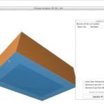
01 – Reference space model created in ArchiCAD 17 to represent needs for chosen environment and analyze determine climate conditions.
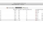
02 – BIM data is entered so reference model is paper thin and not air tight, thereby approximating external conditions.
Defining a reference space with internal thermal properties nearly identical to the external environment is a first step in the process. From within ArchiCAD 17 the user would create a simple space with essentially paper thin walls and structural enclosures of slab and roof. A thermal block is defined as part of this process. (see image 01)
All elements in the reference model space are made of a thin layer of fiber board with a high U-value. The solar absorptance values are set to zero, meaning no solar radiation heat is saved in the material, and infiltration is set to maximum, making the structure in essence similar to being outside. The next step after defining this reference model space is to locate it in the world. (see image 02)
You can locate projects by entering their exact address, latitude, longitude, and altitude, time zone into a project location palette or by locating the project via Google Maps.
Working with Climate Data File
There are two ways to obtain the weather data file. One method is to download it from the StruSoft Climate Server or use another resource such as the United States’ ASHRAE online data. US Department of Energy data files come in zipped file packages and once unzipped can be imported into EcoDesigner STAR.
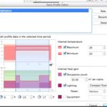
05 – Inputing thermal requirements for building use or program prior to final calculations for reference space.
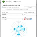
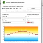
The user interface enables several views of this climate data, across multiple units of time, across each category noted above in the bulleted list (i.e.: air temperature, relative humidity, etc). (see images 03 – 04) The user can view this graphical information to gain an understanding about the project’s climate–and importantly whether it is heating or cooling dominant or mixed. (more on this fact later).
Okay, we have completed two key steps. We have created a reference model–not to be confused with the “baseline” model defined later–and we have located it in the world where our project is. As part of this process we make the reference model out of fiber board and deliberately set values for its physical structure so that it will nearly emulate the outside thermal conditions. It is a type of paper building, if you will. Now the third step is to assign it a operational profile that matches our intended use for the building we are designing in ArchiCAD 17. (see image 05)
It is recommended the user make a duplicate of a operational profile “type” and then edit it with the graphical slider UI options in the Daily Profile Editor. This is the quick way to do this work. (see image 05) Once this is done we assign this operational profile to the new Thermal Block that define our reference energy model.
Finding the Unmet Hours
The whole point of doing this work (with the reference energy model) is to find the annual Unmet Load Hours of the external air temperature, as measured against thermal requirements for the intended new building use.
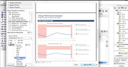
06 – Energy analysis final report shows graphs of reference space performance. In the view above we can see that the required Internal temperature range, in pink, is much higher than the air temperature (blue line) inside the “reference model.” This means that heating would be in demand at this time of year (Feb.) at these hours.
In some places around the world, the outside air temperature matches or nearly matches the internal thermal requirements many days of the year. This would result in very few unmet load hours. In such places on Earth, the demands on thermal properties and configurations of buildings with respect to the energy to heat and cool such structures is quite low or inconsequential. However, the vast majority of architects are building in areas on this planet that don’t fit this situation. (see image 06)
So the forth part of this stage is to calculate the energy performance on this reference energy model. What one learns from, for instance, the sample problem shown in the demo videos on GRAPHISOFT’S website is that the unmet heating hours dominate the situation. This is an important conclusion that will inform the process in later stages.
next page > Energy Model Calibration



Reader Comments
In-Depth: Architosh looks at GRAPHISOFT EcoDesigner STAR | Architosh http://t.co/6Uq6pQYmgO
Comments are closed.