Continued from page 3
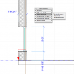
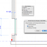
With your model utilizing composites you can set up various views in plan and section and in the new 3D Documents. Sectional views will be vary helpful to structural engineering consultants whereby they can assess their core structure and availability of spatial conditions to the architect’s planned finishes’ limits. The following two views show different dimensioning based on Core Only and Entire Structure settings. (see image 10 -11) You can access this option via menu item Document > Partial Structural Display or via the Quick Options palette, which is the preferred way for us.
As useful as Partial Structural Display is it really takes flight under ArchiCAD 12’s new 3D Documents functionalities. For this part of the review we are again going to turn to QuickTime animations to capture some processes.
New 3D Documents
Firstly, in the first movie we show how to use the “thick marquee” tool which in plan mode selects “all floors and roofs” so as to grab the entire building top to bottom. Within this marquee selection area we are able to create a 3D view of the building in axon-section. (see QuickTime QT-02).
QT-02 – Creating a 3D Document starts with generating a 3D view through any section of the building. You do this using the Marquee selection tool for “All Floors” generating a partial axo cut through the building. From here you can zoom in, orbit/rotate, pan, et cetera. You can also use the Partial Structural Display options mentioned above to further control the view.
The value of being able to produce partial 3D views of your building in section should become obvious to anybody new to BIM. With the Orbit tool one can spin the building around to the view you want, zoom in, pan and setup for more detailed analysis of your work or to setup a dynamic 3D Document. (we’ll get to this in a bit).
Using the 3D Cutting Planes tool you can cut your axon further (in plan horizontal mode now) and toggle between the full building and 3D cut plane. (see QuickTime QT-03). This allows one to zoom into specific quadrants of a building in 3D — to any zone within the building — to capture a 3D sectional condition for further documentation.
QT-03 – This movie continues where the last one left off, creating a 3D Document and showing how to use the 3D Cutting Plane tool to generate the 3D Documents you want. No complex, hard to get to, or understand portion of your building can escape the use of this powerful tools combination. In the next image below we generate live-dimensions, in axo no less, with live-associative keying and notation.
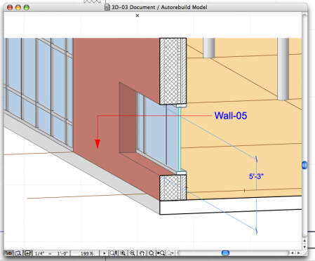
In the movie above we are using our review test file building — which is far from complete — but complete enough to zoom into a curtain wall placed into a larger opening in a thick composite brick wall. Once the view angle is set one can “right-click” and choose Capture Window for 3D Document. This produces a new 3D document which is added to the Navigator – View Map. With this 3D Document you can add text, dimensions and utilize ID labels for your walls, doors, windows, floors and roof components. This information is viewable in various ways and stays live-linked. If you re-assign a wall a different type or composition this information will get reflected in a label on your 3D Documents..as such they remain valuable linked views. (see image 12)

12 – A 3D Document Window. Notice it is not rendered in OpenGL and the composite materials in the wall are fully visible. Labels are live-linked to components and dimensions are fully associative.
3D Documents are nearly the same as 3D views of the BIM model except you can’t navigate them in 3D or orbit rotate them. They are fixed. However, you can right-click on a blank section of the 3D Document window and select the contextual menu item, Open 3D Source and Redefine based on the Current 3D, which can reset your axon view angle, zoom, et cetera.


Reader Comments
[…] Product Review: Graphisoft ArchiCAD 12 | ArchitoshDec 19, 2008 … With ArchiCAD 12 Graphisoft — which is now apart of the German Nemetschek Group – has done major work on a new underlying “systems … […]
Comments are closed.