Continued from page 1
Attaching Rooms and Doors
One of the less intuitive features of OrthoGraph—and yet ironically one of its most important—is the tool that merges or attaches rooms to each other. When you select the Move tool the helper window yields the following text: “Move location. Move, attach and detach rooms to other rooms.”
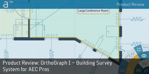
11 – Attaching or merging rooms to each other is how you conform your separate measuring survey exercises into comprehensive building survey layouts. The two doors above are actually the same door in the same wall, which needs to get merged.
While this seems simple enough there are some hidden rules to make this feature actually work simply. If the rules are not met it won’t work simply. In the image above (see image 11) I have purposely located a door in each respective room which actually share a wall. However, the doors—which are actually the same door since they are in the “shared” wall—are located in slightly different positions relative to the nearest corner. When I go to move the room to join with the other room it will fail unless I move it such a way that the door in the room I’m moving (in the process) overlaps the door in the other room. Being that these doors are actually the same they must interlock in this procedure. The walls will join but the corners of the room are now slightly askew. (see image 12)
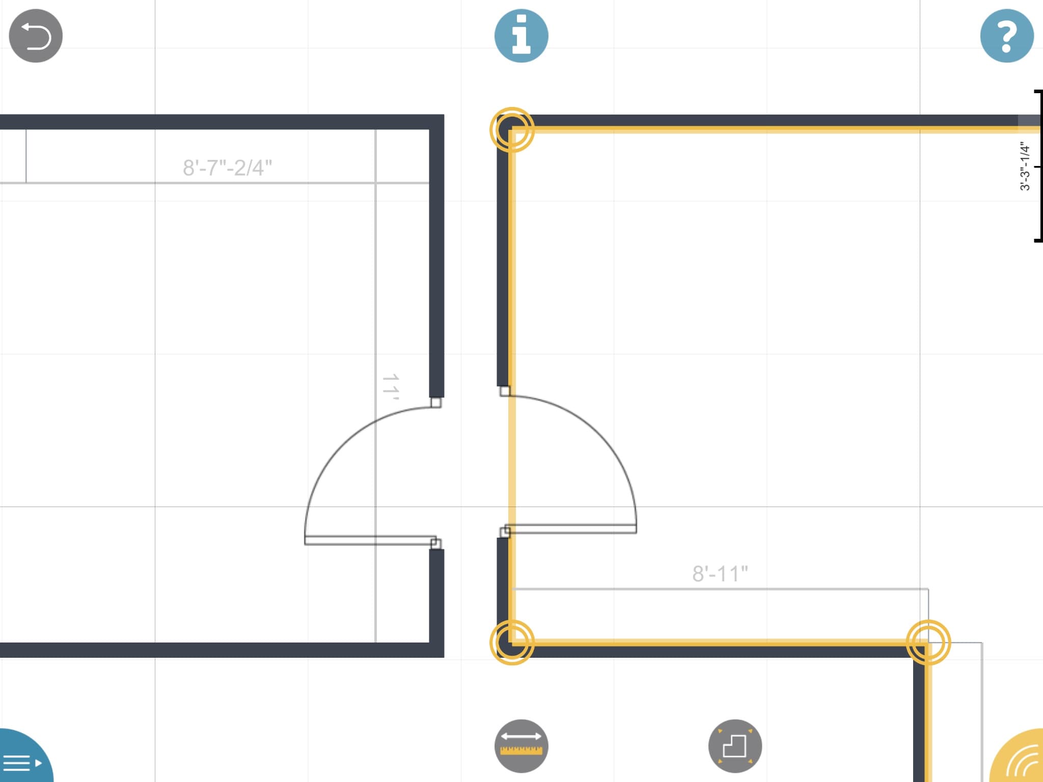
12 – I have joined the rooms by aligning the common door. However, different dimensions to the door from the corner forced this error of sorts. Is it an error? Or is the wall actually not aligned? Your actual survey experience will dictate the answer. Perhaps a room is “padded out on one side of the door only?
The truth is this may actually be accurate. If wall thicknesses vary from one room to the next, the actual dimensions from corner to door from each respective room may indeed very. This is, in fact, how one discovers variances in an existing building that may seem counter-intuitive because in fact the building was built with oddities. A common oddity is the room on the left may have a wall (south in the image) that is “padded” out and thus thicker. (we will get to wall thickness in a moment).
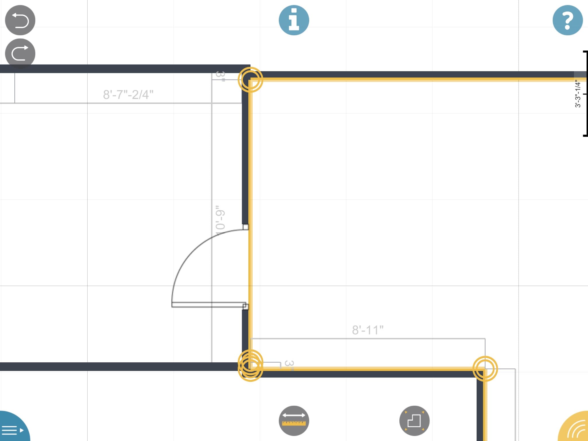
13 – If differences do exist but you know from the field the walls must align at least structurally, place a common dimension for the door from the corner (2 feet in my case). Then factor a pad-out by adjust wall thickness later.
Re-entering the dimension back to 2 feet to match the other room’s position for the location of the door will allow me to re-join the room the way I believe it must be in actuality. (see image 13) You may notice from the images above that the common door had a competing door swing direction—which direction does the door take? OrthoGraph will choose one and it may be the incorrect one. To fix it you must edit the door object itself.

14 – The door object settings popup dialog is clever and easy to work.
15 – The door is now flipped to the other (correct) side.
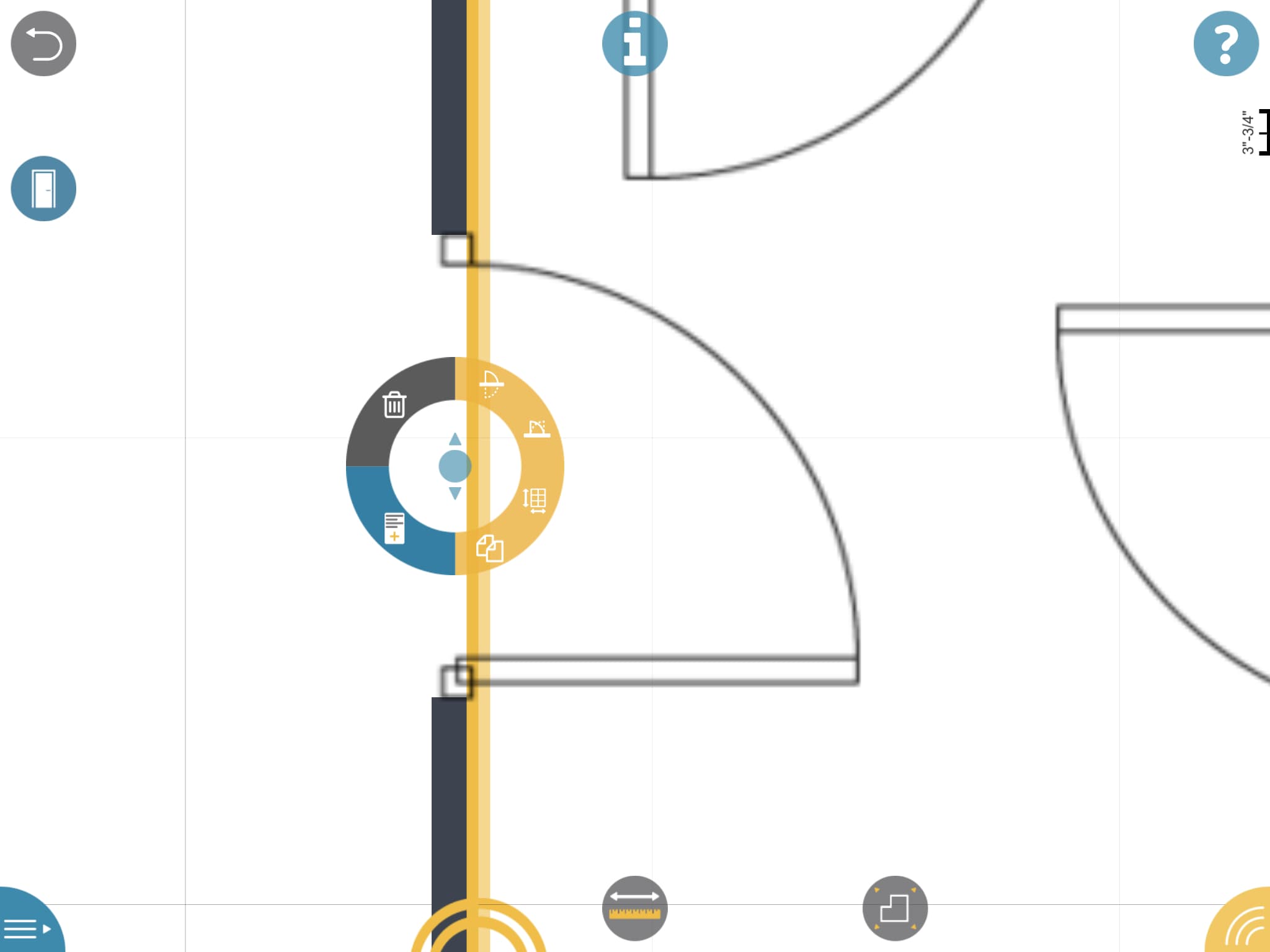
The next step is to select the “pencil” tool or the “door” tool and tap the area defining the center of the door in the wall. A circular (donut shaped) dialog will pop up with 6 buttons. Four buttons are in the yellow zone, while one is in the blue zone and the trash can button is in a dark gray zone. (see image 14)
By the way, “blue” as a color in OrthoGraph I’s user-interface stands for information and also distinguishes the main menu from the main Toolbar fan wheel. In image 15, the first yellow icon shows the door flipping to the other side of the wall. The next icon flips the swing direction only. The next icon looks like a grid with dimension control—it changes the size of the door. The next icon looks like two documents on top of each other–it copies and paste the door into the next point you touch on a wall. (see image 15)

16 – The blue doc looking icon takes you to this properties sheet for that door.
The blue icon will enable us to view and edit data about the door. (see image 16) You can also enter a barcode and take a picture and provide custom properties. Finally, the trash can icon deletes the door altogether.
Using the Leica Disto D2 For Measurement Input
The only difference in using your LDM for inputting dimensional values in your OrthoGraph I survey app is that when you drag between two points, like described and shown above, you do so while your LDM device is connected to the app. To make sure the LDM is connected turn it on and make sure Bluetooth is activated. Next, hit the “Main menu” button. Then select “Connect to” and choose a device manufacturer. OrthoGraph I will list devices it finds. Select yours. It will turn yellow and say “Connected.” (see image 17)
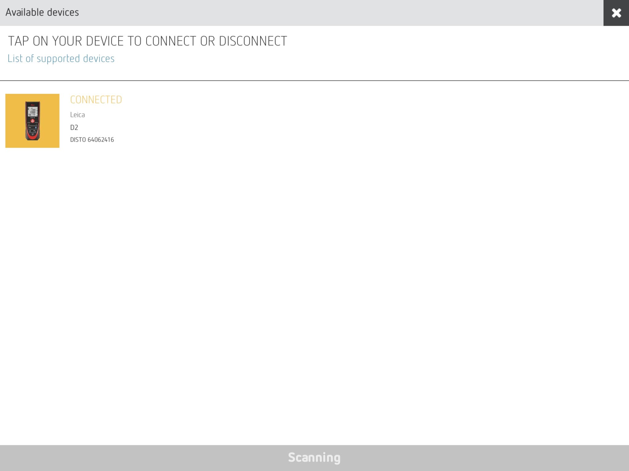
17 – This is what OrthoGraph I looks like once your Bluetooth LDM is connected to the app.
Hit the “X” button to close the setup window and you are returned to the drawing screen. Zoom into a wall you want to measure. Tap the measurement icon (it turns blue). The anchor point and the second measurement point (the two vertices) are highlighted as shown in this image below. (see image 18) A dimension is currently displayed but once you shoot your laser device and hit the conclude button on the device, that “value” is wirelessly sent to the app and the value is changed in the app dialog. Select the confirmation checkbox button (in yellow) to confirm. The drawing changes automatically to reflect the new position and values.
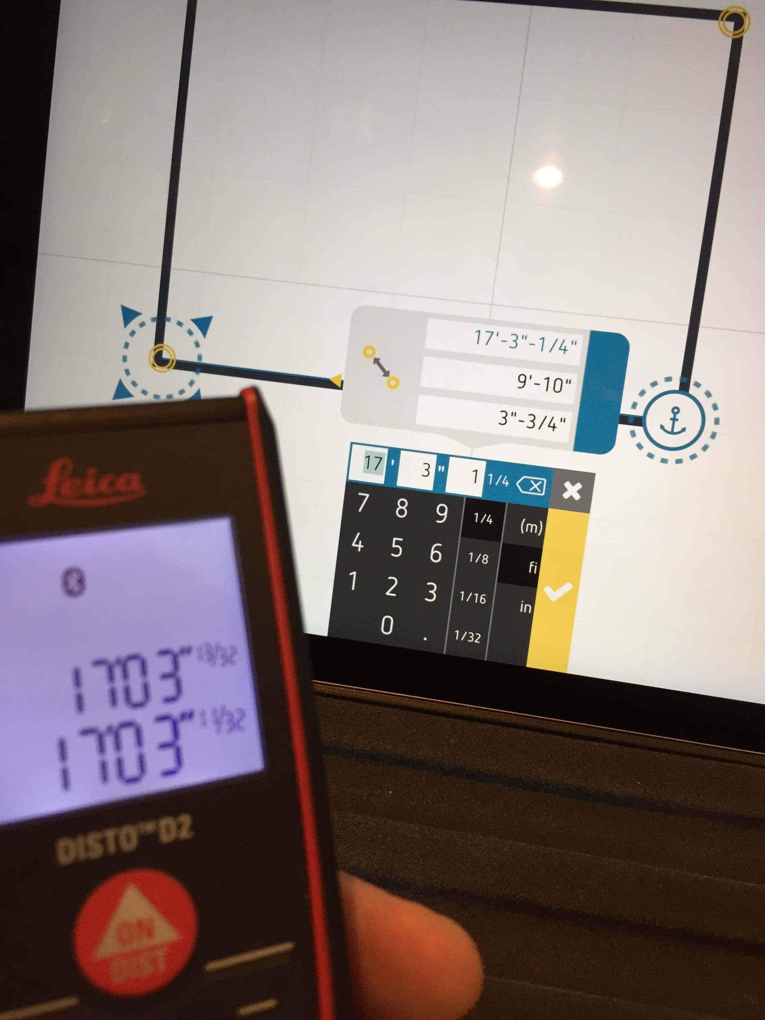
18 – Successfully connected you take laser measurements, in my case with my Leica Disto D2, during the measuring input process. The distance values from the device are sent to the app wirelessly. So cool!
Repeating this process you can rapidly measure (survey) huge rooms all by yourself, including rooms that include hazards you can’t walk by or over, or span over large openings to below or gaps in structural floors due to fires or other destruction. This app actually improves safety at the building site because you use the laser to span over areas you should not be trying to span over with your body and limbs.
You can locate doors and windows in your walls the same way. Select the “Object” icon, then the “Door” icon, then hit a wall where the door should be. Then hit the measurement icon (it turns blue). The door object has two vertices defining its left and right edges of the door (or frame size but not inclusive of the frame). Again, using the LDM device start the process of measurement and obtain the dimensions by aiming (placing) the LDM at the left edge of the door and then pointing back toward the wall. For the D2 you have choices for where the dimension starts—from the back or front of the device. I prefer the back. Placing the device back in alignment with the door shoot the laser dimension.
next page: Wall Thickness and Windows & Exporting Data

Reader Comments
Comments for this story are closed