No Engineering Skills Required
Like many architects out there, I was personally very curious about EcoDesigner STAR when it was announced. I was curious to learn how it would provide energy simulation data sufficient for the USGBC LEED building certification process, widely adopted here in the United States. A LEED Accredited Professional myself, I know first hand how demanding the overall subject matter can be and how many architects routinely shy away from integrating sustainable design directly into their practice.
Many architects rely on external consultants for sustainable design. Often for several reasons. Chief among these is a deep concern to provide their clients optimal performance benefits, which they may feel they cannot provide at the same level as dedicated consultants in this domain. Even architects who are LEED APs themselves very often rely on such consultants.
Let’s face it. Architects didn’t get into this field–in most cases–so they could become technical energy experts. They became architects because they love design.
After spending hours reviewing EcoDesigner STAR materials, including an excellent video series over at GRAPHISOFT, and talking to the company directly about this new product, I am confident architects who learn about EcoDesigner STAR will feel more optimistic that integrating sustainable design directly into their practice and iterative design process is both worthwhile and more attainable than they previously believed.
GRAPHISOFT has done a tremendously good job at creating an energy simulations and analysis software that any architect can master. No engineering skills required.
Getting Started
Let’s get started by reviewing what EcoDesigner STAR is and what it can do first and foremost. Then we can walk through the program’s abilities and the specific process in more detail.
- EcoDesigner STAR is a “built-in” BIM to BEM (building energy model) workflow
- EcoDesigner STAR is built into ArchiCAD 17 and a license unlocks the feature set (no download required)
- Built using StruSofts‘s VIPcore calculation engine — it complies with ANSI/ASHRAE Standard 140-2007
- EcoDesigner STAR meets the requirements ANSI/ASHRAE Standard 90.1 for LEED system credits
On this last point. ASHRAE 90.1 (as it is often referred in short) Appendix G defines the method for designing for the LEED EAc1 (Optimized Energy Performance) credits for both NC and School and Core and Shell projects, wherein a “baseline building design” is defined to meet the minimally compliant standard.

00 – EcoDesigner STAR allows architects to perform thermal bridge analysis in just seconds with a 2D heat-flow situation. This is useful and can help determine where condensation issues may arise.
LEED EAc1 – Optimized Energy Performance, is by far the most important credit in the LEED certification system based on number of points (10) available towards your project. And for architects there are four options to pursue credits for EAc1. Option 1 is “whole building energy simulation” which is what EcoDesigner STAR conforms to. The other three options are essentially prescriptive-based and yield at most up to 5 points–and they don’t apply to “all building types” like Option 1 does.
Here are other features of EcoDesigner STAR:
- Program does Thermal Bridge Simulation
- Handles On-Site Renewable Energy
- Exports BIM geometry and thermal property data — PHPP, iSBEM, VIP-Energy, gbXML and Green IFC file formats
- Can fine tune energy design right down to the Thermal Block level
- Can be used for projects in any climate on Earth
EcoDesigner STAR by GRAPHISOFT is currently available in the United States, Canada, United Kingdom, Australia, Denmark, Sweden, The Netherlands and South Africa. These markets largely reflect countries with the most advanced green building standards, codes and rating systems.
Some Interesting Notes about EcoDesigner STAR
Miklós Svéd, Product Manager for EcoDesigner of GRAPHISOFT reminded us that the state of the art in common practice is for an architect to more or less complete a building design and then engage a consultant to performance energy simulations and documentation work for accreditations. “This often means the energy analysis consultant is rebuilding the BIM model inside their energy analysis software,” said Svéd. “With EcoDesigner STAR the architect can begin the energy simulation process much earlier in the design process.”
We also learned from our discussions with Svéd that the Strusoft VIP calculation engine behind EcoDesigner STAR has several decades of development behind it, and that GRAPHISOFT itself has invested five years into EcoDesigner STAR. The net effect of this is that EcoDesigner STAR is incredibly fast. Miklós Svéd noted that for a large building the software program EnergyPLUS may take two days to perform all its calculations, whereas EcoDesigner STAR will only take 3 hours.
Advertisement
This speed advantage serves to encourage early use of EcoDesigner STAR in the architect’s workflow, enabling multiple passes of simulation analysis that can then inform the design process.
In the remaining sections of this article we provided a detailed summary of the actual workflow of working in EcoDesigner STAR. Reading the rest of this article will take about 30-40 minutes. Optionally, readers can also watch all six videos (about 3 plus hours) here at GRAPHISOFT and obtain the same information. Naturally we encourage you to read our article. You can always peruse the videos later.
The EcoDesigner STAR Process
The process of utilizing EcoDesigner STAR with ArchiCAD 17 for the architect who is interested in energy simulation and analysis, and especially those interested in LEED certification or other similar standards, consist of these primary steps:
- One – Perform Climate Analysis
- Two – Establish Baseline Building model
- Three – Identify the relevant Low Energy Architectural Solution Sets and serially evaluate Performance Benefits on Proposed Design
- Four – Define Building Systems for Baseline Building and Run Simulation
- Five – Apply Appropriate Solution Sets for Building Systems and Renewable Energy Systems to Proposed Design
- Six – Compare Energy Performance between Baseline and Proposed Designs
In the following pages we run through this complete process, end to end.
next page > Climate Analysis Stage
Climate Analysis Stage
In the Climate Analysis stage of the EcoDesigner STAR workflow a key step is to create a simple reference building model, define the location of the climate of the project, set the main profile for the operation of the building, run an energy simulation, and use the generated reports to document the climate statistics. (see image 01) This workflow or series of steps helps the architect or designer choose a set of sustainable design solutions that are appropriate to the specific project.
In order for a complete Climate Analysis to be executed, all of the following content needs to be determined, and for Annual and Monthly Lowest, Highest and Average values:
- Air Temperature
- Relative Humidity
- Solar Radiation
- Wind Speed
The EcoDesigner STAR user obtains this information directly from the online weather file. With that in-hand, calculating the required Degree Days for heating and cooling becomes automatic from the program and assist the architect in the design process. Specific systems, materials and even the shape or configurations of buildings will all factor into calculations for Unmet Load Hours (in heating and cooling).
For architects who need a brush-up on the definition of Degree Days, here it is: the integral of dry bulb temperature as a function of time, relative to a base temperature. The heating and cooling requirements for a given structure at a specific location are considered to be directly proportional to the number of Degree Days at that location.
A special form of the Unmet load hours calculations can also be performed as part of the climate analysis process. Unmet load hours are what it sounds like: number of hours during the year when the internal temperature is out of the comfort range defined in the building operation profile.
At the beginning of the design process–when the above mentioned design data is not yet available–the Unmet load hours calculation can be executed, using the climate analysis reference space model to study the natural thermal comfort characteristics of the project site’s climate versus the internal thermal comfort requirements.
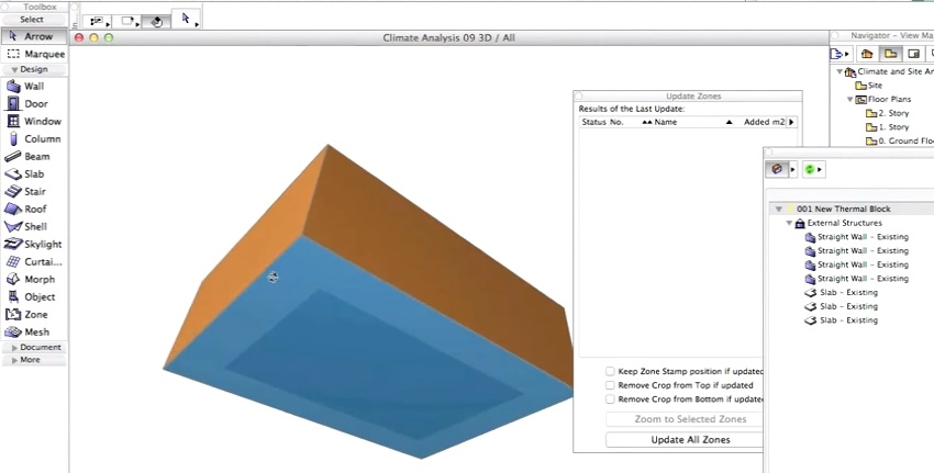
01 – Reference space model created in ArchiCAD 17 to represent needs for chosen environment and analyze determine climate conditions.
02 – BIM data is entered so reference model is paper thin and not air tight, thereby approximating external conditions.
Defining a reference space with internal thermal properties nearly identical to the external environment is a first step in the process. From within ArchiCAD 17 the user would create a simple space with essentially paper thin walls and structural enclosures of slab and roof. A thermal block is defined as part of this process. (see image 01)
All elements in the reference model space are made of a thin layer of fiber board with a high U-value. The solar absorptance values are set to zero, meaning no solar radiation heat is saved in the material, and infiltration is set to maximum, making the structure in essence similar to being outside. The next step after defining this reference model space is to locate it in the world. (see image 02)
You can locate projects by entering their exact address, latitude, longitude, and altitude, time zone into a project location palette or by locating the project via Google Maps.
Working with Climate Data File
There are two ways to obtain the weather data file. One method is to download it from the StruSoft Climate Server or use another resource such as the United States’ ASHRAE online data. US Department of Energy data files come in zipped file packages and once unzipped can be imported into EcoDesigner STAR.
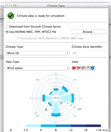
03 – Climate data file is imported into EcoDesigner STAR and can be graphically reviewed.
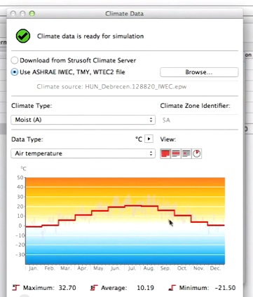
04 – Climate data showing air temperature data.
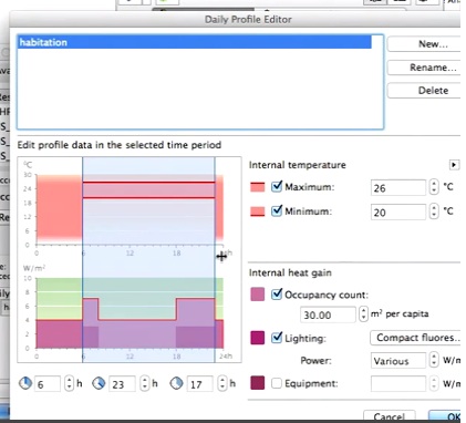
05 – Inputing thermal requirements for building use or program prior to final calculations for reference space.
The user interface enables several views of this climate data, across multiple units of time, across each category noted above in the bulleted list (i.e.: air temperature, relative humidity, etc). (see images 03 – 04) The user can view this graphical information to gain an understanding about the project’s climate–and importantly whether it is heating or cooling dominant or mixed. (more on this fact later).
Okay, we have completed two key steps. We have created a reference model–not to be confused with the “baseline” model defined later–and we have located it in the world where our project is. As part of this process we make the reference model out of fiber board and deliberately set values for its physical structure so that it will nearly emulate the outside thermal conditions. It is a type of paper building, if you will. Now the third step is to assign it a operational profile that matches our intended use for the building we are designing in ArchiCAD 17. (see image 05)
It is recommended the user make a duplicate of a operational profile “type” and then edit it with the graphical slider UI options in the Daily Profile Editor. This is the quick way to do this work. (see image 05) Once this is done we assign this operational profile to the new Thermal Block that define our reference energy model.
Finding the Unmet Hours
The whole point of doing this work (with the reference energy model) is to find the annual Unmet Load Hours of the external air temperature, as measured against thermal requirements for the intended new building use.
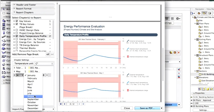
06 – Energy analysis final report shows graphs of reference space performance. In the view above we can see that the required Internal temperature range, in pink, is much higher than the air temperature (blue line) inside the “reference model.” This means that heating would be in demand at this time of year (Feb.) at these hours.
In some places around the world, the outside air temperature matches or nearly matches the internal thermal requirements many days of the year. This would result in very few unmet load hours. In such places on Earth, the demands on thermal properties and configurations of buildings with respect to the energy to heat and cool such structures is quite low or inconsequential. However, the vast majority of architects are building in areas on this planet that don’t fit this situation. (see image 06)
So the forth part of this stage is to calculate the energy performance on this reference energy model. What one learns from, for instance, the sample problem shown in the demo videos on GRAPHISOFT’S website is that the unmet heating hours dominate the situation. This is an important conclusion that will inform the process in later stages.
next page > Energy Model Calibration
Energy Model Calibration
In the GRAPHISOFT video dedicated to this topic, a reference model from the ASHRAE 140 standard test cases (Case 960) is used to demonstrate the energy model calibration workflow: a new building model in ArchiCAD that matches the standard’s specification is created and then an energy calculation is run. Finally, these calculation results are compared with the reference values recorded in the standard.
There are many cases such as Case 960-ASHRAE 140. The EcoDesigner STAR calculation results match the reference values for each case which validates GRAPHISOFT EcoDesigner STAR and its use for producing the required test documentation for various energy standards and certifications, such as LEED, in general.
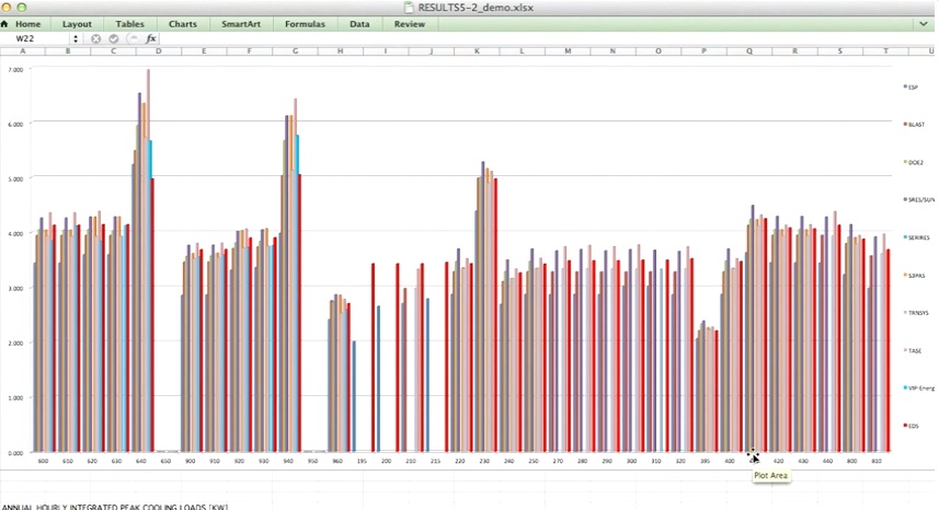
07 – EcoDesigner STAR compares favorably and reliably against other energy analysis software that meets ASHRAE 140 standard.
EcoDesigner STAR is the only architectural BIM software tool that delivers complete energy analysis tools, directly inside the architectural BIM authoring environment, that rival third-party engineering software for energy design professionals like mechanical engineers. The graph above shows EcoDesigner STAR (red bars) measuring against all the leading energy simulation software programs developed for engineers. (see image 07)
Because EcoDesigner STAR complies with ASHRAE Standard 140, it means that it can be used to perform complex energy analysis and simulation successfully and its results meet the requirements of the LEED rating system, GreenStar, and other similar energy performance rating and certification systems that reference ASHRAE Standard 140. (see images 07-09)

08 – EcoDesigner STAR compares favorably and reliably against other energy analysis software that meets ‘ASHRAE Standard 140 for computer energy simulation software.’
Nevertheless, each energy model is unique, and therefore project-specific energy model calibration is also advisable. The user is encouraged to calibrate every BEM project against validated benchmark values that represent the energy performance of similar building(s) at the same location.
The workflow of energy model calibration on the project level is similar to the method applied to the ASHRAE 140 standard test cases; obtain reference building energy performance documentation, run energy simulation on the ArchiCAD model and finally compare the simulation results with reference documentation. The locally available benchmark values will most likely be less well-documented compared to the benchmark values of ASHRAE 140 but they are usually good enough to check whether the simulation results are “realistic.”
This is the easiest way to maintain the validity of energy models throughout the entire design process and to make sure that all calculation input data are entered correctly–an important aspect of dynamic building energy simulation, where tens of thousands of input and output data are processed for every hour of the calculation reference year.
In the upcoming paragraphs, a sample case from ASHRAE 140 test series (Case 960) is used to demonstrate how to review calculation input data and how to check whether the calculation results make sense by comparing them to known benchmark values.
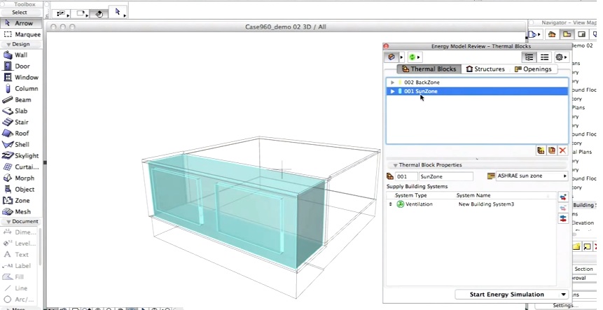
This is “model level” calibration and ASHRAE Stardard 140 provides a test (Case 960) with known values which can be compared against once run through ArchiCAD 17 with EcoDesigner STAR. Case 960 includes a specific model structure with an unconditioned loggia type space in front of a fully conditioned enclosed space. (see images 08 – 10)
09 – ASHREA test Case 960 input and model validation steps.

10 – ASHREA test Case 960 input and model validation steps.
This calibration BEM (building energy model) can be quickly produced in ArchiCAD 17, which means that all the envelope and physical properties from the Case 960 standard can be input into the software. From within EcoDesigner STAR the user can select from a list of available operation profiles and select this standard–including ASHRAE un-conditioned sun-zone and ASHRAE conditioned back zone. (see images 08-10)
Demand Calculation Mode
The process of energy model calibration at the early stage of the design process usually only requires “demand” calibration. In order to execute the demand calculation, choose “Not Yet Specified” for all building system settings. This means you avoid specifying your HVAC plant equipment at this stage of the design, assuming that the heating and cooling systems are capable of meeting all the requirements with 100 percent efficiency. Annual and peak heating and cooling energy demands are among the results of this calibration. Besides energy model calibration, this type of result data can also be used for building system sizing at a later design phase.
After replicating the test model in ArchiCAD 17–which can be saved as a file for future use–you input all the key data from the standard and then run an energy analysis test. ASHRAE publishes a minimum and maximum result in mega watt-hours which each compliant software must be capable of hitting a value between the published range.
Again, the steps in this stage are:
- Obtain Reference Documentation
- Input data that matches standard into EcoDesigner STAR
- Run energy simulation
- Compare results with reference standard documentation
In the next stage we look at evaluating energy performance for the actual building design.
next page: Evaluating Energy Performance on Your Building Design
Evaluating Energy Performance on Your Design – Three Stages
Baseline Energy Calculations
At this stage of the architect’s design process she has completed a climate analysis report, determined Unmet hours to determined if the project is more heating climate dominated, cooling climate dominated or a mixed climate dominate structure. Secondly, she has executed a building energy model calibration on a preliminary version of her design.
In the next phase the architect would take a copy of her early design solution, as modeled in ArchiCAD 17, and modify it to create a baseline building without systems. Meaning, no highly developed envelopes, curtain walls, roofs, floors and other complex systems including shading, solar collection, et cetera. Why you may ask?
Advertisement
Because in EcoDesigner STAR, like other tools, one needs to run a “Demand Calculation” first and review the “baseline building’s” general energy performance prior to final development and system selection. And for ASHRAE 90.1 reporting for LEED certification later, this “baseline building” is critical to the whole building simulation method required of LEED EAc1 Option 1.
It’s important to note as well that the architect’s building design at this stage may change in some basic ways, such as rotational shifts, grade changes relative to building levels, fenestration reconfiguration, et cetera, but the baseline building is defined in such a way in ASHRAE 90.1 Appendix G that these types of changes do not affect it.
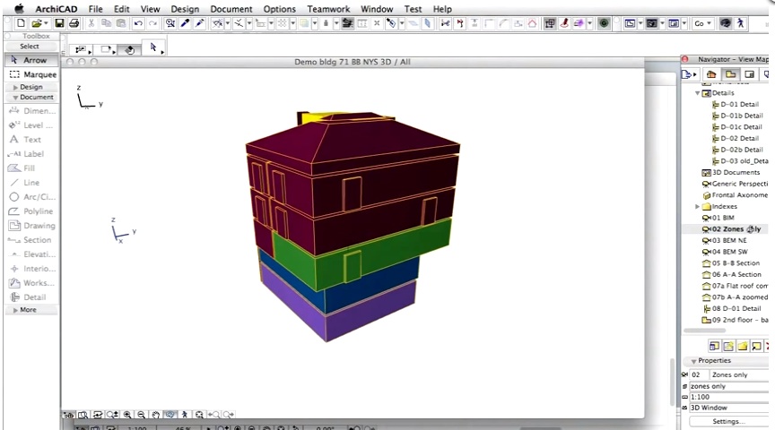
11 – ArchiCAD zones are show inside the Navigator view.
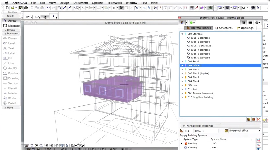
12 – Thermal blocks are ArchiCAD zones grouped together, for energy simulation purposes.
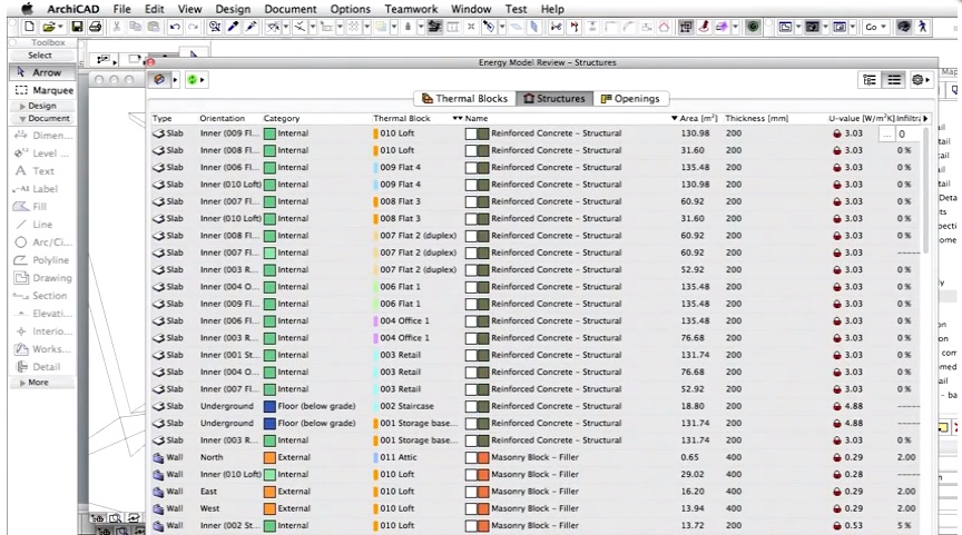
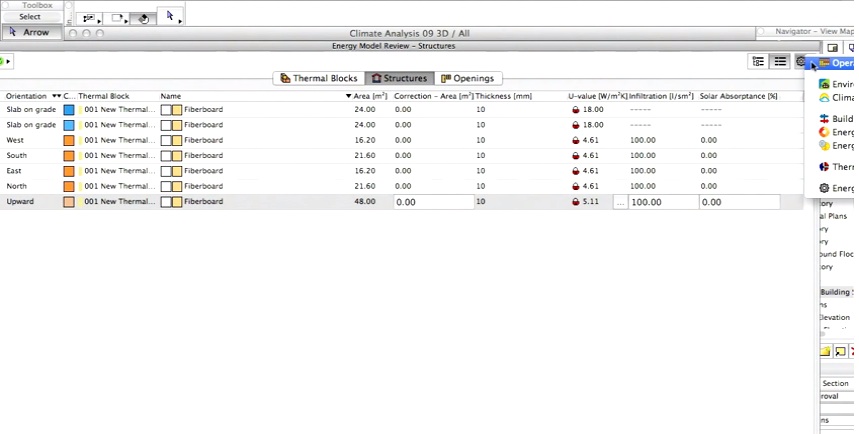
13 – Inside a list view of the BEM looking at physical elements and their thermal properties.
From the Energy Model Review palette you can view a BEM’s Thermal Blocks, Structures and Openings (see three tabs in the interface images above). Each thermal block is a group of zones that share the same orientation, operation profile and building systems (latter is not yet relevant in the demand calculation phase). Thermal blocks are defined by the user and, color coded in the energy model review. Under the Structures tab the user can select on individual elements, visualize them on the 3D view of the building energy model and review and edit their thermal properties like U-value, Infiltration rates, et cetera. (see images 11-14)
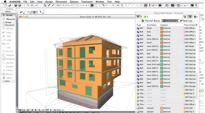
14 – Under the Structures Tab one can view the entire BEM in a color coded model view.
At this stage no buildings systems have been defined, as the calculations coming up are meant to rate the energy performance of the architectural design alone, independent from the building systems solutions, which one utilizes later in the process.
Low-Energy Building Solution Sets
Low-energy building solution sets are a concept that emerged from the Solar Heating and Cooling chapter of the International Energy Agency Task 40 Research Group (IEA/SHC Task 40 research). It categories low energy building solutions in an easy-to-understand way so that they can be applied successfully in the design process.
The solution sets are derived by researching hundreds of low-energy and net-zero buildings and comprising solution set strategies. For example, in excellent net-zero or low-energy buildings in “cooling dominated” locations, 100 percent of them optimized building form and 100 percent of them had advanced envelope designs, while only 50 percent of them utilized thermal mass strategies.
The architect must go back to the original climate analysis calculations and look at unmet hours and decide if their project’s location is more heating dominant, cooling dominant or a mixed case. Particular solution sets for each case dictate what best strategies to test next for enhanced thermal performance.
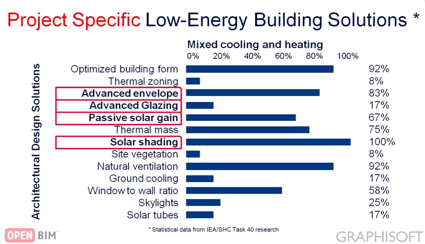
15 – Low-energy Solution Set for a Mixed Heat/Cool zoned building location, like central Europe.
Sensitivity Analysis means that the architect can individually analyze and compare specific low-energy solution set components (e.g.: thermal mass or advanced fenestration systems) one by one, implementing them on their preliminary building design. After each set element, an energy simulation is run and the report is reviewed to compare the effects of that strategy. With each solution set component evaluated this way, an architect can select which solution set components to implement on their project on the basis of: construction budget, availability of materials and specific skilled labor, impact on design aesthetics and client considerations.
Low-Energy Demand Architectural Design
As the first step of low-energy demand architectural design, the architect decides on the best possible project-specific architectural design solution sets and proceeds to now analyze their design further, including better detail design at thermal breaks. With the baseline building now analyzed and behind us and with a solution set now strategically implemented the architect can basically re-run a “demand-oriented” calculation on the proposed design and compare it against the baseline. The baseline building serves as a reference point for comparing not just individual solution set components against but for a total strategy comparison.
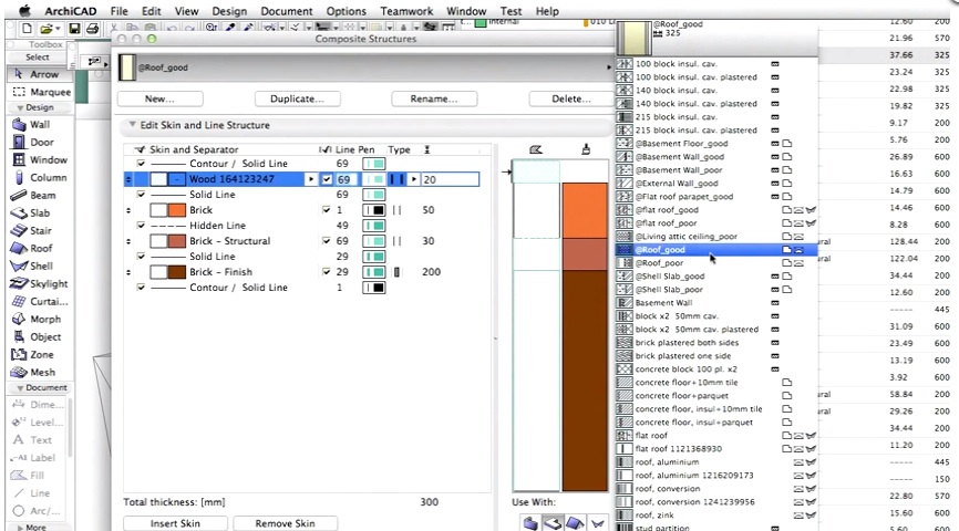
16 – This view shows the improved composites for the wall system, with improved thermal performance for the proposed building design.
After the energy analysis is run on the updated building design, (see image 16 above) with implementation of the low energy architectural solutions sets, one can comparatively review the Proposed Design results side-by-side with the Baseline Building Results. This view shows heating, cooling, service hot water, ventilation fans, lighting and equipment energy demand values and a Savings column marking percentage improvement between proposed and baseline designs. (see image 17)
17 – A side-by-side comparisons of baseline building and proposed design shows the net benefit analysis of low energy architectural solutions.

18 – Improvements in detail and better composite systems means improved thermal transmission.
Additionally, we can also do comparisons at the detail level and analyze improvements of thermal transmission. Take a look at these side-by-side thermal views of the baseline building at left and the proposed building at right. The increased exterior thermal insulation system added to the clay walls dramatically improves the dynamics of the thermal break at the concrete balcony slab to main building slab. (see image 18)
next and final page > Whole Building Energy Efficiency Optimization
Whole Building Energy Efficiency Optimization
The final phase of working in EcoDesigner STAR is focused on applying real building systems for cooling, heating and ventilation, lighting, et cetera for both the baseline building and the proposed building. Remember, the proposed building has low energy architectural solution sets applied to it to reduce its energy demand, therefore building systems with smaller capacities can be applied. In the case of the baseline building, larger HVAC equipment is necessary to provide similar comfort conditions.
To get started the user applies building systems for cooling, heating or ventilation to each conditioned thermal block. Unconditioned thermal blocks, like unconditioned basements for example, would not getting heating and cooling systems but might get ventilation systems. (see image 19 below)
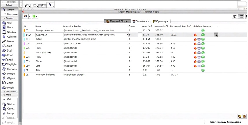
19 – View of Thermal Blocks in the Energy Model Review palette, where you assign building systems to individual thermal blocks and then configure choices for each system.
This is a product for architects and their technical staff and EcoDesigner STAR does not require its users to have detailed knowledge of HVAC building systems–the kind of knowledge that a mechanical engineer would know. That is important to emphasize here.
Also, the demand calculations for the energy model system sizing have already been run earlier for both the baseline and the project design versions at this design phase. (see Demand Calculation section earlier).
Once you have completed this process on the baseline building you repeat the process for the proposed structure. Only this time you apply recommended low-energy building systems and renewable energy systems recommended by the IEA/SHC Task 40 research noted earlier. (see chart in image 20 below)
Use the Sensitivity Analysis approach and apply each system one by one to determine the most appropriate–project specific–combination of low energy building solutions and the corresponding return on investment.
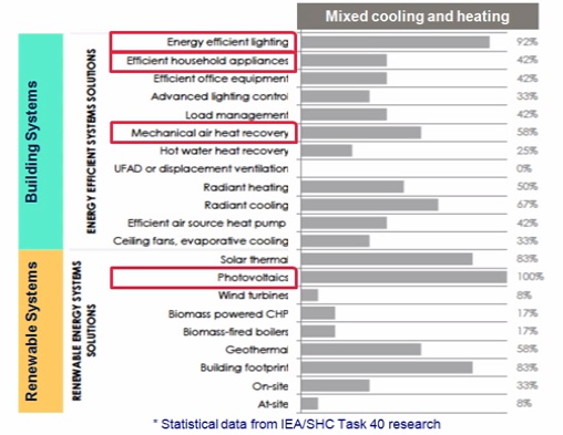
20 – Low-energy building systems and renewable energy systems stats and recommendations for mixed cooling/heating situations from IEA/SHC Task 40 research (image courtesy of Graphisoft)
The project-specific combination of low-energy building systems are then applied to the proposed building BEM (building energy model) and EcoDesigner STAR runs the energy simulations calculations again.
Reporting for ASHRAE 90.1
For the ASHRAE 90.1 performance calculations the baseline building must be rotated by 90 degrees three times and the calculations must also be rerun each time. (see image 21) This establishes an average, which ASHRAE considers more valuable as it rules out specific architectural configurations which can effect energy and chiefly represents the “average design solution” better for the purposes of the ASHRAE 90.1 standard. This produces the ASHRAE 90.1 (LEED Energy) reference data required for the LEED process.
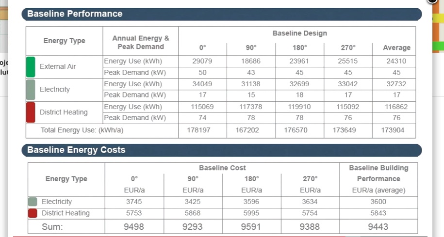
21 – EcoDesigner STAR automates the ASHRAE 90.1 standard requirement to rotate the baseline building three times at 90 degrees, calculate the energy performance of each variation and average the results to generate the energy performance rating, baseline reference data.
At the same time, EcoDesigner’s automated rotation and calculation support is a great tool for architects during the early design phase too. From scanning quickly at the baseline building’s rotated results one may gleam useful information about orientation advantages that should then possibly be pursued in the proposed design.
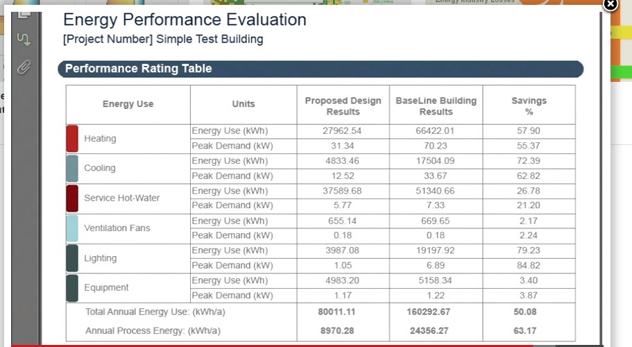
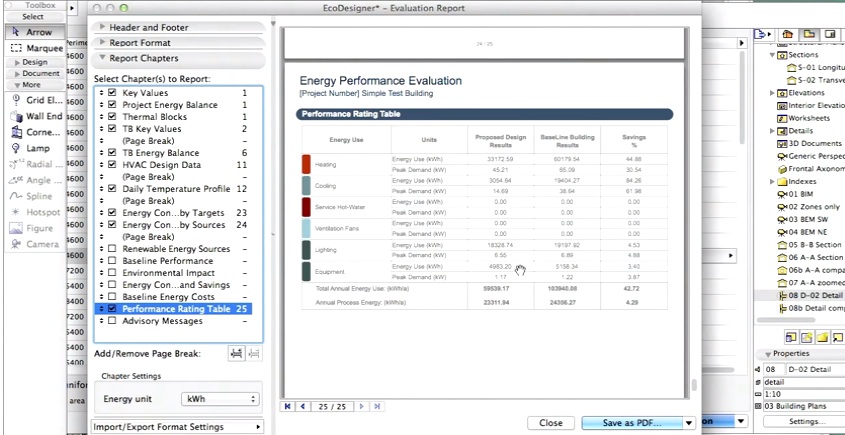
22 – Building energy performance rating report showing savings in the Proposed building’s energy costs compared to the baseline data.
The last image we show is a final energy simulation comparison between the baseline reference data and the energy performance of the proposed design. The energy used for heating, cooling, service hot water, ventilation fans, lighting and equipment is summarized for both baseline and proposed, with grand totals for Total Annual Energy Use and Annual Processed Energy. (see image 22)
As you can see in the chart above, Savings, shown in the third column, can be significant between the proposed design with Low Energy Solution Sets applied via a Sensitivity Analysis and the baseline building which only meets the minimum requirements. (see image 22)
Closing Comments
As we noted back in 2009 when GRAPHISOFT introduced EcoDesigner for ArchiCAD, the goal of the software is to “advise” the design process and provide another dimension to the BIM environment for the architect in shaping his design. As such, what continues to set both the early EcoDesigner and current EcoDesigner STAR apart from the competitive solutions is the intimate placement of this technology directly into an architect’s BIM authoring environment–right where he or she can make the best decisions at the earliest stage of the design.
Sustainability is all about choices. And 80 percent of design choices affecting energy efficiency are made in the early design phase. EcoDesigner STAR is positioned to strategically address this fact unlike any other tool on the market. —– ANTHONY FRAUSTO-ROBLEDO, AIA LEED AP