Ever since we learned of solidThinking, way back when, the computer-aided industrial design (CAID) tool has intrigued us as a possible architectural conceptual modeler application. Why?
Well, for starters there are not a lot of Mac-native advanced surface modeling applications in existence and most of the best tools for industrial and product design have traditionally been on Windows. Sure, there are some noteworthy exceptions on the Mac. I can hear readers saying, “well, what about this, what about that?”
And you are right.
This isn’t a product review, so in all fairness we should mention some of the most noteworthy exceptions. These would definitely include the near legendary formZ from AutoDesSys, Inc., and the equally venerable Ashlar-Vellum family of products–all of which were born on the Mac, no less. But solidThinking came later to the Mac OS platform…and, as such, many Mac designers and architects are not yet familiar with this application.
The second reason why solidThinking might be interesting for architectural modeling is because it has some unique abilities. solidThinking Evolve provides a super tight and efficient environment that combines powerful yet approachable organic surfacing, construction history and integrated rendering. It’s this particular combination of these three features–with some of solidThinking’s special abilities–that caught our eyes years ago and had us thinking about the tool for advanced architectural forms.
Frank Gehry Like Surfaces
One of the cool features we noticed early with this program–a program that is purpose built for designing things like cool bicycle helmets–is how easy it is to manipulate a few basic parameters and quickly iterate a dozen or so times within a few minutes. Additionally, we also noticed several releases back that the program came with these glossy, metallic surface shaders which made for visually interesting architectural forms. The kind of work Frank Gehry has become world famous for.
The latest version of solidThinking Evolve 2014 just was released in late February. As noted before this isn’t a product review. We will hopefully do a complete product review of Evolve 2014 in the months ahead. The purpose of this feature article is to demonstrate and explain how a NURBS-based surfaced modeling tool, one oriented at the product design space–can be used for architectural concept modeling.
Early Steps – Curved Object Basics
Using solidThinking Evolve for conceptual architectural modeling assumes something. Namely, it means you are interested in complex surfaces in architectural design. This means more than just circular-based domes and vaults…or drums or walls on radii.
However, to start out you actually may begin with such shapes, as in the example we will lead with below. In this case we are going to start with a sphere. (see image 01). Now for those who maybe wondering, before doing conceptual architectural surfaces modeling work in Evolve, they may want to set their units in the preferences to something larger in scale. The default setting, if memory serves, is centimeters. solidThinking doesn’t do feet and inches together like traditional architectural tools like say SketchUp, formZ or a BIM program. If you choose feet you will need to work in decimals of feet for your inches work.
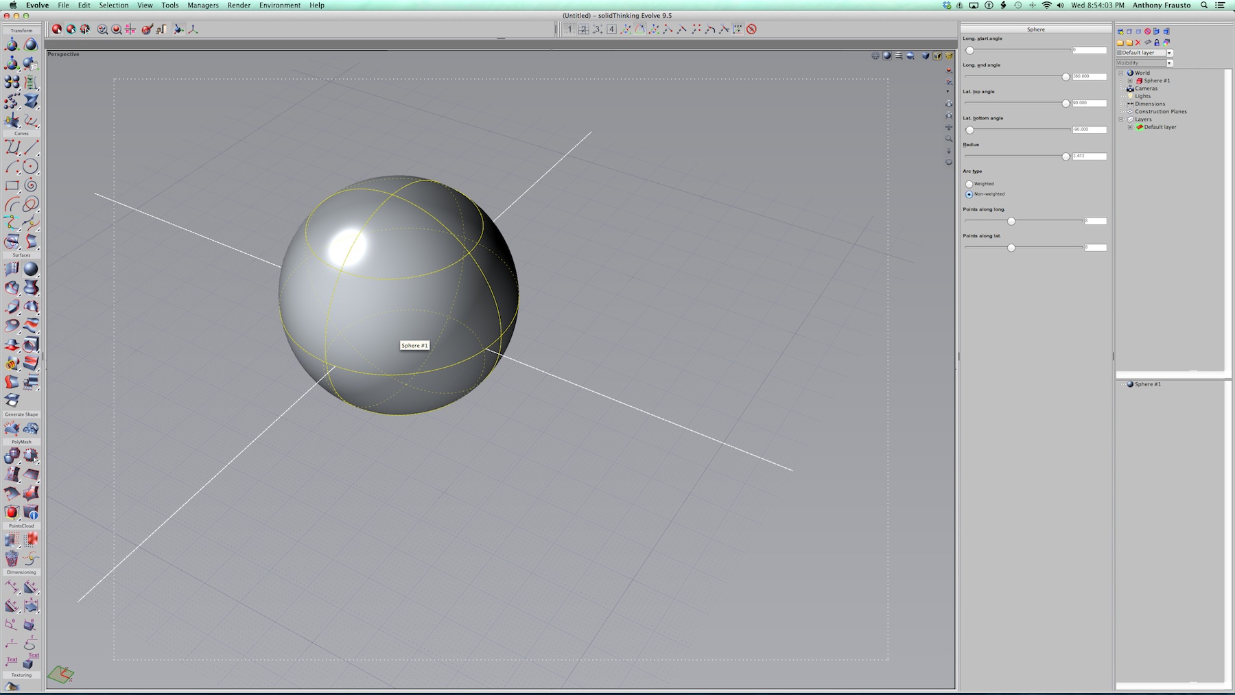
01 – the solidThinking Evolve interface with a sphere chosen. The UI is traditional in that there are tools on the left, organized in a traditional two-col. format, with inspector, layer, construction tree and scene management palette zones on the right of the main viewports.
For our work we chose meters as our unit and for most architects or architectural design professionals working in most places beyond the US metric units like meters would work well.
What we have in front of us above is a 90 meter wide sphere. And we are going to play with its shape using some of the most straight-forward tools in Evolve. This will serve as an introduction to the basic methods of the program. In solidThinking Evolve we can choose from a variety of primitives which have various parametric controls. For a sphere, the parametric controls consist of its radius, top and bottom latitude angles and a few more. Let’s review three levels of editing the sphere in the images below.
There are three object selection button icons on the top left. (see image 02) The first one is for single-clicking, selecting an object. It will pre-select highlight in dashed yellow lines (everything in the UI is customizable so this color could be changed) and once selected shows in solid yellow lines. Object parameters can be edited in the object inspector palettes on the right (see image 03) where items like radius, in this case, and latitude and longitude start and end angles can be adjusted to create various alterations to the basic sphere. (see image 04)
02 – Single click selection of a cube. Three selection modes shown in three left most icons.
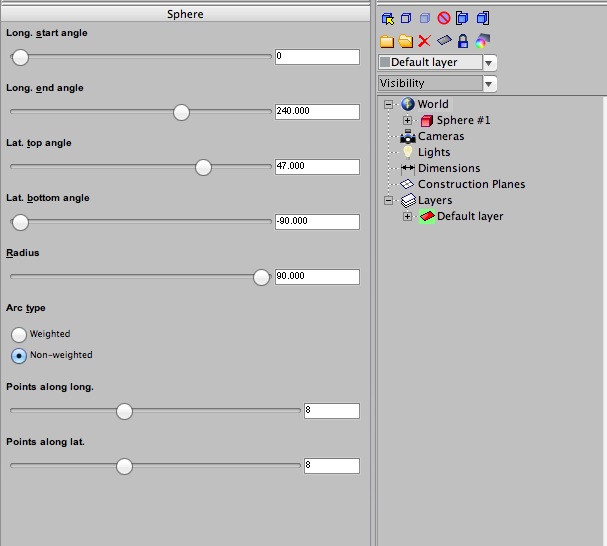
03 – Objects can be parametrically edited across a range of parameters.
04 – This sphere has been edited across several of its parameters, including top latitude angle and longitude start angle.
We have explored the left most selection icon and the second most left selection icon. That second icon is called the Select Parameters button. Double click an object to enter this mode or use this tool button. Parameters of an object are displayed in light blue and can be selected by the mouse and dragged to enter or change values. Or you can enter values into the palette or use the sliders. (see image 05)
The third button is called the Editing Points tool button. With this button you can edit individual points along hull lines, shown in green. Hull lines are a convenient way to select all of the control points that lie along an object’s isoparm. If you are wondering what an isoparm is we can explain. (see image 06)

05 – In object parameter edit mode the “parameters” of an object are highlighted in light blue. You can select them and drag on them to edit values or control those values in sliders or a text box within the right palette.
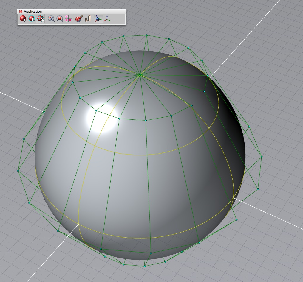
06 – In object edit points mode green hull lines array control points that lie on an object’s isoparm. You can individually select single or multiple control points and edit their location in space to dramatically change the nature of forms.
The word “isoparm” is short for “iso-parameter” which itself is referring to the way a surface is calculated. Iso comes from the Greek isos, which means equal. So think of the statement parameter equals and thus “isoparm” defines the characteristics of simple and complex surfaces.
Next page: Working in Points Mode and Shaping a Complex Roof
Working in Points Mode
One of the coolest features of solidThinking Evolve is that you can work directly with points along an isoparm and still have parametric controls for the entire object. The result is a unique combination of modeling control and exploration. At some point you reach limits with the parametric values depending on the control point edits.
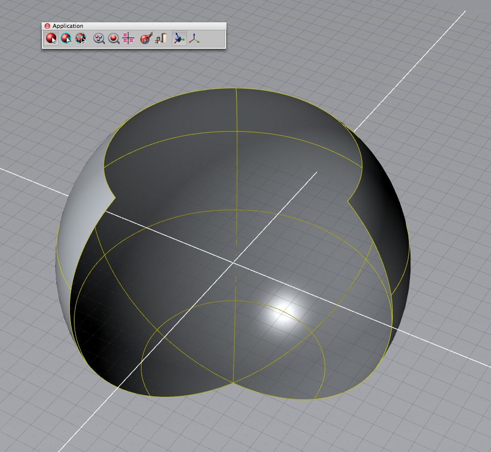
For instance, you can select multiple control points on a series of hull lines (say to the right side of this sphere). Hit the control key to select multiple points. Now using the translate tool, move those points along one axis (and you can type in a specific value). We can convert our sphere to an egg shaped form quite easy. Actually, it looks more like the nose of an airliner. (see the video below).
There are many ways you can explore a form with just working with points mode and strategically moving points on a hull line. Working with a basic shape like a sphere a more complex form can be created and imagined for various purposes.
Shaping a Complex Roof
Let’s start getting more literal with architectural form making. These days it has become more common to see buildings with curved undulating roofs. In the next example a NURBS curve was drawn on one of the upright axes (Z or Y). A copy and paste procedure instantly invokes the Translate tool. Successive copies are arrayed over a series of low horizontal planes which stand in formative shorthand for wall planes. (see image 08)
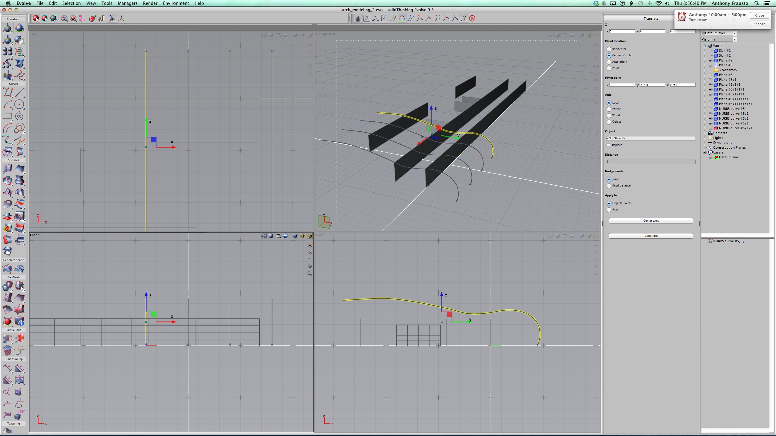
08 – Roof form drawn over a low pavilion building.
One of the things we should also point out about the image above is the four-quadrant viewport arrangement. This is standard in solidThinking. Each viewport can be made to take over the entire screen space and each viewport can be set to different views. The default is shown above (top, right, left, perspective, etc). And each has its own zoom, pan and field of view and dolly settings. (image 08)
There are many surface modeling tools in solidThinking Evolve. The most useful include the Loft, Loft 8.5, birail and skin tools. The Skin tool was used to create the roof form above and below. Simply click the Skin tool button and follow the instructions in the interface prompts. (image 09)
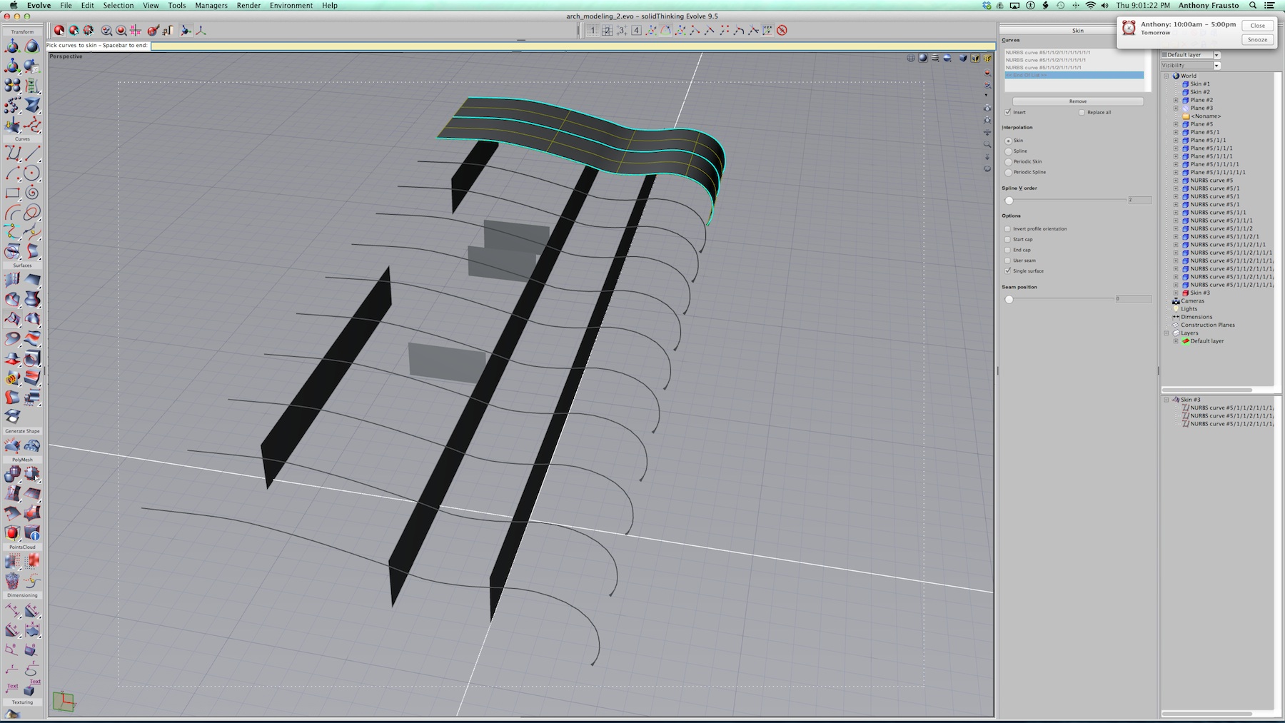
09 – Skinning tool in action. Clicking on a series of NURBS curves creates a continuous plane. The curves can be unique in shape and size, unlike our uniform curves.

10 – The completed roof structure and rendered in the small Render Window with Raytracing on.
In our particular example a sheet-metal like skin appears as a curvilinear roof over a low building. We have also shown a rendered view but in this article we don’t have time to discuss the integrated rendering options in solidThinking Evolve. You can learn more about them here. (see image 10)
Skyscraper Design
One of the more exciting uses of solidThinking Evolve is in the area of conceptual skyscraper modeling. Since the program is quite fast in creating complex surfaces from splines and NURBS curves, like in the roof example above, one could imagine turning that on end and this time “altering” a series of NURBS curves arrayed vertically into the sky.
To start we will go back to our sphere example. But this time just use a circle. Like the circle that is intrinsic to a sphere–the one we altered by drag-selecting a series of points in edit points mode to create a more egg like shape–this time we will symmetrically alter a circle to create an ellipse like shape. (see images 11)
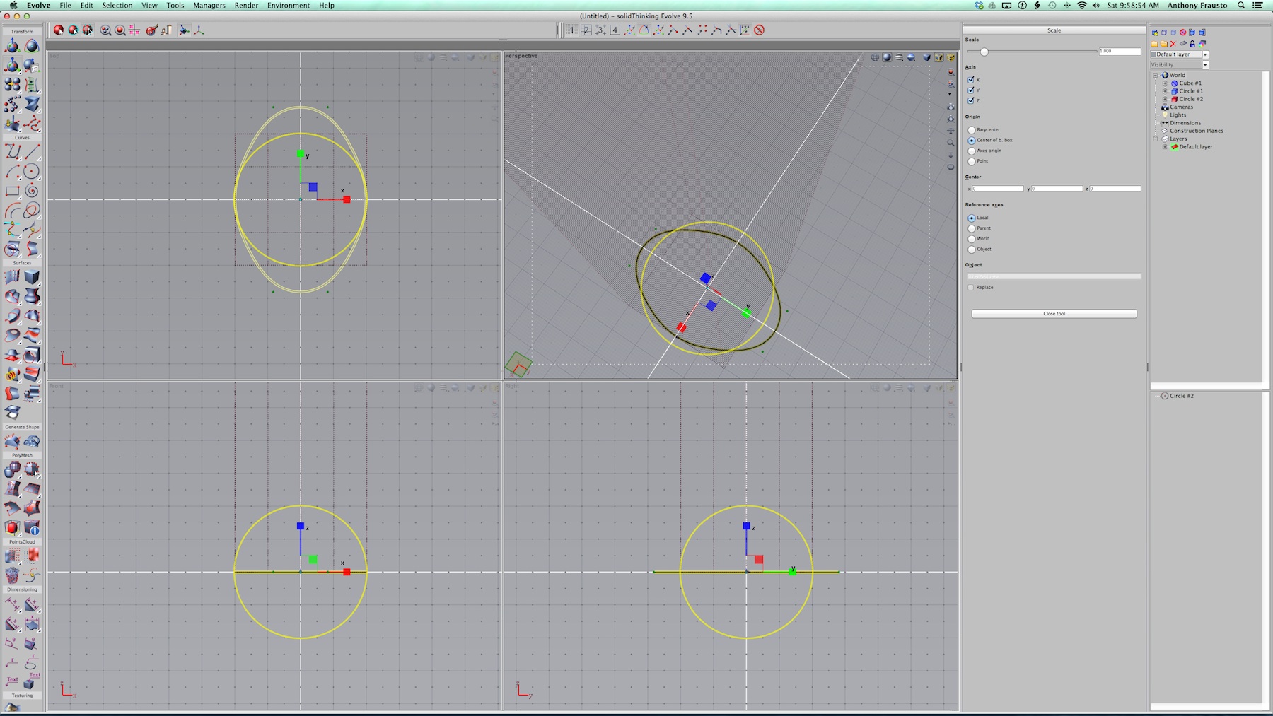
11 – We are altering a circle to create an ellipse like curve for a series of alternating floor plates for a 300 meter tower.
To execute this we first created a 40 x 40 meter x 300 meter tall tower form, to serve as our volumetric, height and width guide. We then turned it a plum color and made it semi-transparent and made picking disabled. These are functions and actions we will either cover in a review or Part 2 of this series later.
To get a series of elliptical control floor plates one enters edit points mode and selects the circle. Then drag box highlight the sets of points on the isoparms north and south of the circle on the Top plan viewport upper left. Once highlighted, selecting the Scale tool separately move these points by dragging them outwards from the center of the circle.
A neat feature of solidThinking Evolve is that even though you violate the basic shape of a primitive, you don’t completely destroy its parametric features. What we do next is copy-paste drag translate each curve up 50 meters on the tower. Then, selectively alter the radius for each curve–which began as a circle. By altering the radius of the circle, which is the basic first shape in the history of that curve, the entire curve responds uniquely to the translation. This is a much faster way of getting iterative shape options into play.
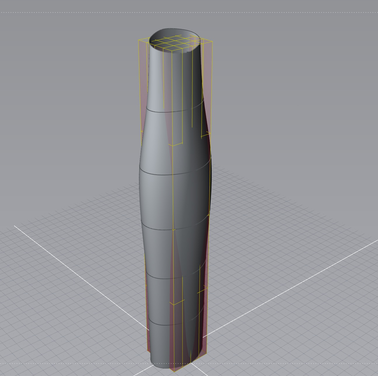
12 – The tower’s skin is closed using the skinning surfaces modeling tool.
In the view about you can see the early first version of tower 1, as measured against the reference geometry we created by the 40 x 40 x 300 meter form in plum. To get the slanted top we rotated the last elliptical curve at the top. (see image 12)
Post Formation Iteration
The procedure and methods shown from the beginning of this article have helped us arrive at the conceptual skyscraper tower form shown above. (see image 12). Now here is where the power of solidThinking Evolve comes more into play. It is quite easy to reshape this modeled surface. We can also copy and paste two more versions of this tower. When we do so the complete history tree and all the parameters associated with this form’s construction move with it. With multiple versions we can create as many options as we want and be able to view them side-by-side and in context.
We are only scratching the surface in this article on what solidThinking can do for pre and post formation of designed forms. We have constructed our towers. Now we can play around with the forms themselves.
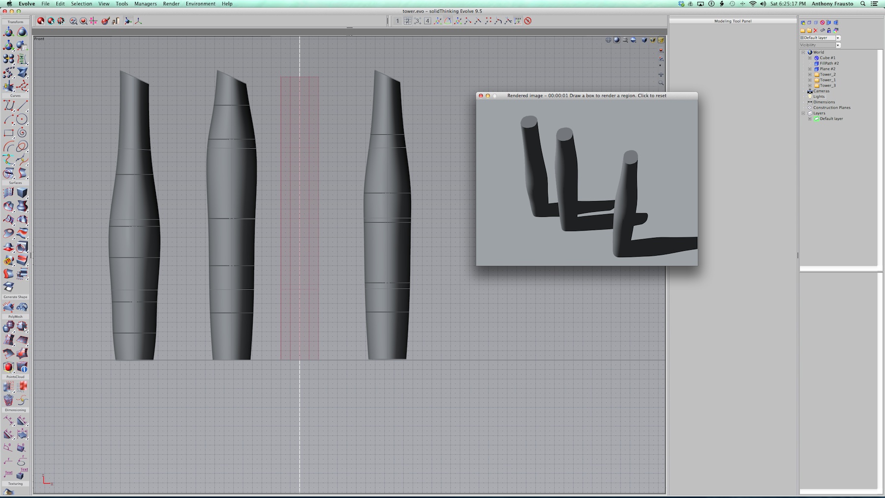
13 – Three versions of the skyscraper tower form have been shaped.
In the image above we have three different tower forms, each based off the original. A ray traced view is also shown. solidThinking Evolve supports a Maxwell Render option as well as a new Luxion KeyShot option in Evolve 2014. In this side view we can compare and evaluate. I personally like the two tower forms on the right and will show you why after the jump.
Also on the next page I will show you an animation of the process in action.
next page: An Animated Look and Further Contextualizing
An Animated Look
There are three key tools for working with the alteration of forms and elements in solidThinking and they are the same core three used in other similar programs as well. They include scale, translate (move) and rotate.
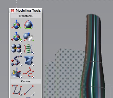
14 – The upper left is Translate, the Upper Right is Rotate and the second on the left is Scale.
In the original sphere we selected individual points and selected the Translate tool. This tool allows you to move one or more elements along constrained axes. By dragging out a few points on the sphere we turned that form into something more like the nose of an airliner.
The Translate tool is also the tool that automatically pops up when you copy and paste objects, since the copy ends up in the same place as the original, you need to slide it out to see it. This enables you to do direct numerical duplicates placing them a set unit distance from the original across different axes. The third tool, the Rotate tool, was used for the top most elliptical curve to yield the slanted top on the tower forms. With just these three transform tools, two surface modeling tools, two curves tools and some rendered output all of this work has been generated. (see image 14)
In the animation below we demonstrate the use of picking two of the curves in the middle tower. The selection is happening inside the world browser but one could also select the tower itself. However, it is faster in the WB. Watch as the form changes interactively and watch as the metal reflective shader used in this OpenGL view shows the nuances of the form move.
To view the videos full screen you can click on the expand icon lower right corner. To get back to the article hit the escape key on your keyboard.
Final Comments
For several decades now changes in structural engineering approaches and the use of computer-driven manufacturing have more easily enabled implementation of complex surfaces on buildings. The type of tower structures imagined in this article are not terribly different than say what the UK architect, Lord Norman Foster, created at 30 St Mary Axe, “the gherkin” in London. (see image 15 below)
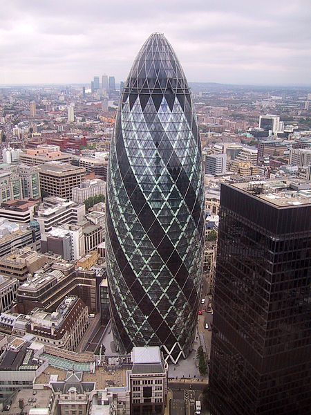
14 – The Gherkin in the UK by Foster and Associates, Architects. (Wikipedia Commons GFDL, 2007)
For skyscraper design in particular it will be interesting to watch where Altair-owned solidThinking Inc., goes in the future, as the company (both solidThinking the subsidiary and Altair Corporation) have made overtures to this market. In fact, Altair has a new focused AEC group.
From talking to the company since last year’s AIA National Convention, we know that the company has been working with AEC giant SOM, utilizing new FEA technology aimed at tall building design in particular. We believe their is ambition to bring some of its expertise in engineering and FEA to the tall structures space. The idea is that architects could model tall building designs of considerable complexity quite quickly and Altair can bring its FEA technologies down to the early stages of design to provide more rapid feedback.
Already the company merges engineering technologies into solidThinking Inspire with its OptiStruct technologies. In the meantime, while all of these possible futures in their tool suite exist, today solidThinking Evolve 2014 provides architects an intriguing and powerful option for advanced curve surfaced building designs. While it is not the only tool in town, as we said in the beginning, it is one tool that the AEC market has only recently begun taking long strolls with.
To learn more about solidThinking Evolve visit here: www.solidthinking.com