It is worth noting that Altair Engineering’s leading edge CAE (computer-aided engineering) software technology has already been utilized by leading architects working globally, by firms such as SOM (Skimore, Owings & Merrill, LLP), for years now. In such cases it is Altair’s market-leading OptiStruct® tools powering advanced front-end structural analytics informing design.
Inspire for Architecture
Inspire has three key aspects to it with regard to architecture. The first is that the tool can be used to generate interesting and unexpected forms which often take on a bio-morphic quality to them (as you will see later in the article). The second is to use Inspire to help create lighter weighted structures. This can mean the whole building or components of the building at both the large and small scale. Lastly, Inspire 2014 can be used to help architects develop structural detailing that is innovative and expressive.
The Article in Three Parts
In Part 1 of this article we will look immediately at how Inspire 2014 works for load type situations in architecture to help create lighter weighted structures. In Part 2 we will then show and discuss some of the ways Inspire can generate truly innovative morphological forms for architectural design, including some real examples. Finally, in Part 3 we will review a particular problem for architectural detailing of a structural nature to help architects create interesting solutions.
Part 1: Creating Lighter Weighted Structures in Architecture with Inspire
In our recent review of solidThinking Inspire 2014 we cover the basics of working in Inspire and we also demonstrate this process with something architects intuitively understand—the structural dynamics of a simply-loaded beam.
MORE: Product Review: solidThinking Inspire 2014
Architects are not typically trained in using any type of sophisticated computer software tools for studying structural engineering. The architect’s goals are to understand the principles of engineering so that designs are, from the onset, reasonably feasible and express a fidelity to the facts of physics. Typically, for licensing exams architects must understand both general and lateral structures topics at a fundamental level only.
These days sophisticated computer software enables structural engineers to visualize forces, loads, and a structure’s response to its environmental conditions, including seismic. The purpose of bringing some of the sophistication of computer-aided engineering (CAE) to the front-end of the design process is to principally avail to the designer a deeper understanding of his design decisions as to how they will eventually bear on the project structurally.
By knowing more earlier, the architect can exercise both more freedom in expression while having a realistic constraints feedback system inform the conceptual design work.
While not specifically designed for the purpose, even the “normal modes” analysis features of Inspire 2014 can help provide architects with deeper understandings around structures—as in the example of a conceptual skyscraper below.
All structures tend to vibrate at particular discrete frequencies. Dynamic loads, like fluctuating airflow, will cause structures to vibrate. (see skyscraper model example, image 01, below). With the analysis tools it is now possible to visualize displacement (animated as well), factor of safety, percent of yield, tension and compression, maximum shear stress, von Mises stress, and major principal stress—all in solidThinking Inspire 2014.

01 – analysis of normal modes on a conceptual skyscraper structure.
This will be of some use to architects doing tall buildings at the conceptual stage. In our sample conceptual skyscraper tests, using real-world dimensions and applied lateral wind forces, the results of the analysis provided conceptual insight into how the structure might actually move and why.
A caveat should be stated here that this to-scale tower in Inspire 2014 is of course fully solid and no such building is. It could, of course, be hollowed out, but the point of the exercise was to see how this full-scale model in Inspire would respond to a normal modes analysis, revealing relationships between its form and a normal modes analysis. Given its particular shape the tower bends and twists as indicated. (see movie below).
In the video above we can see a frequency analysis using the normal modes calculation feature and then have it animated, revealing various movement on the structure due to an array of lateral loads.
A Basic Roof Truss Problem
In the actual review article (which we recommend to read also) we started with something any architect can understand, a simple-loaded beam. In the next few examples we’ll look at a roof truss type problem.
To start we’ll make a basic pitched roof condition. (see image 02 – 03 ). The idea here is to create a volume which represents the space where a truss would carry and resolve its loads to its supports. The depth of the space equals the tributary load area, roughly 24 inches. Next a block is created on top of this to load forces onto. Inspire works better when loads are not directly placed on the “design space” but like the example skyscraper tower above, one can in fact load forces directly on a “design space.” (see the related product review for more info on a “design space” in Inspire 2014.)

02 – A basic roof truss setup problem.
03 – The optimized result from the first run after some modifications were made. The target mass reduction was 30 percent of design space volume.
If a load block is going to be fully supported under a “design space” then there is no real reason to make it particularly thick. In fact, by doing so you add weight if the material for that load block is a metal. It is kept thin in this case. Next, support blocks are created at the ends where the truss would meet a beam or wall support. (image 02)
To apply a force or load you use the Loads/Supports tool. A realistic pounds per square foot pressure is evenly applied to the top load blocks (model elements in grey). Then an optimization is run. The resultant model is shown above (image 03). As you can see, the top load blocks act as if welded to the “design space” optimized mass and form a composite structure, thus becoming a type of top chord, if you will, of the final solution.
Advertisement
What becomes interesting is the resultant optimized mass itself. We end up with a bowed or arched bottom chord with angled struts at the top. This optimized mass shape could next be refined for a real bowed bottom chord truss design, if that’s the direction one wanted to go with the truss design.
A Bracket Problem
In this next example a bracket support (or set of supports) is imagined for holding up a potential snow load on a shading device (brise soleil) on a building. In this example what is modeled is a support block for transferring the load (of snow) that would be carried to the supports for the brise soleil (shown in grey). The brise soleil itself is not designed or modeled.
In the first image the “design space” is setup. (image 04 – reddish brown) An even load is placed on the top block and it gets transferred through smaller blocks resting on the “design space” itself. Load supports are added at the bottom and the side, as attachments to the facade (wall) or ground.
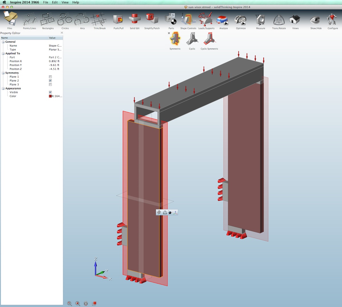
04 – A brise soleil type loading problem is created. The “design space” is where the brackets will take shape.
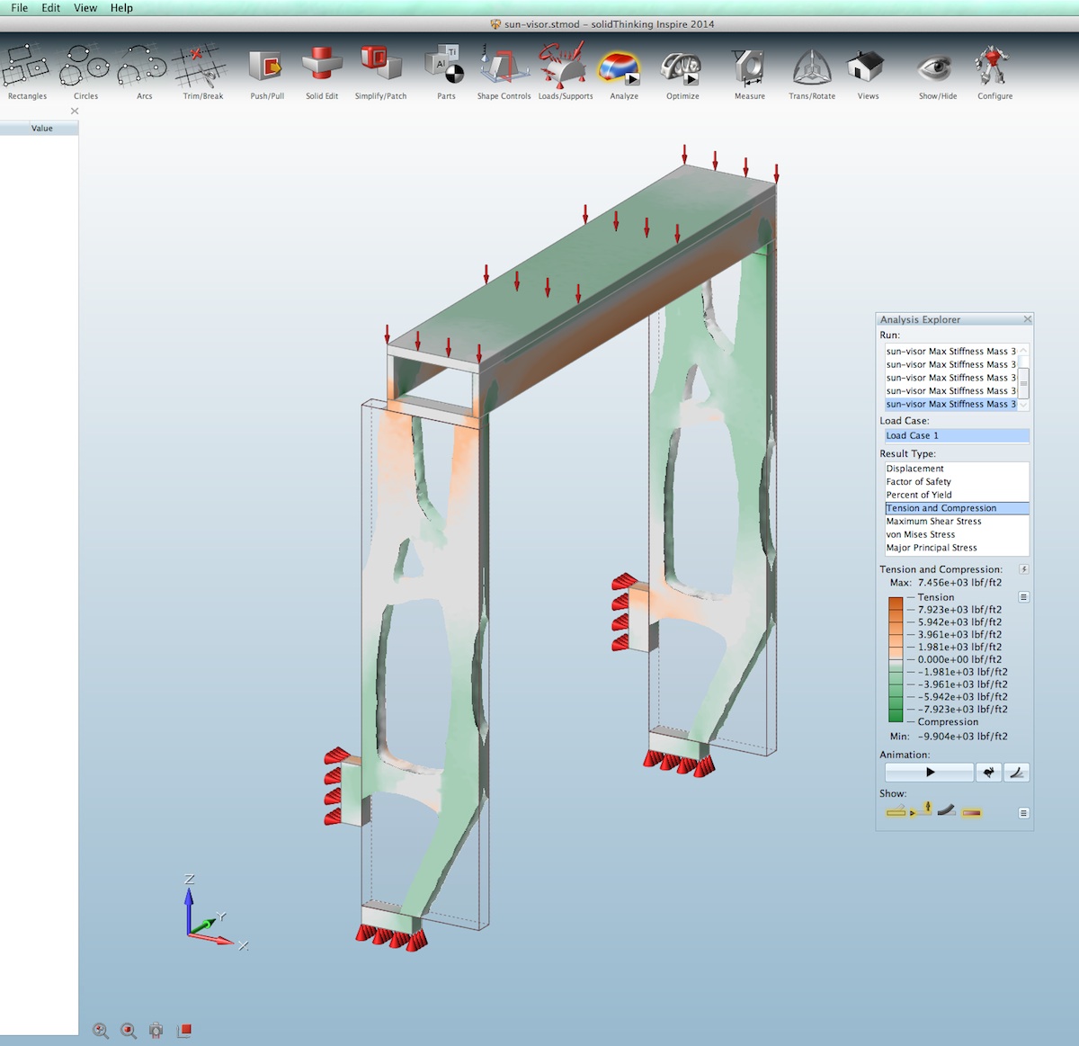
05 – The first set of runs shows this analysis run on a resultant shape.

06 – In this modified design the resultant optimization run ignores the lower supports entirely.
Because we are not sure how the loads will be passed through the “design space” and what resultant optimized form/mass we may get, the support on the side is first placed low on what would be the wall. Next, an “optimization run” reveals an interesting truss like shape. (image 05). Not happy with the stress at the top of the optimized shape in image 05, and its oddly unattractive overall geometry, a new mass optimization run took place on the same load but with an “added” support at the wall towards the stressed sections of the first result. (image 06)
The resultant optimized form resembles an interesting bracket-like shape and the lower support locations are totally abandoned (as determined by Inspire 2014)). A thicker mass is left up at its top towards the back-end facing the wall side. The resultant geometry is quite clean-looking and the lower leg to the lower wall connection could be quite interesting. From this result an architect may then further develop a steel bracket support for a brise soleil that, at certain times of the year, may be asked to carry a substantial load due to seasonal snow loads.
Let’s now look at some truly interesting morphological form examples, including a built project from Inspire.
next page: Innovative Morphological Form in Architecture
Innovative Morphological Form in Architecture
It is not possible for this author, in the time of testing software and writing a review, to truly work up some fascinating morphological architectural form using Inspire 2014. Therefore, we will be looking at a few things that solidThinking Inc. sent in for the article.
Bus Stop Structure
The following example is from a user in Europe and was sent to us by solidThinking. The structure is all concrete with reinforcing and it is so biomorphic that it seems almost alien. In our other photos of it below, you can see how beautiful the daylight drapes the rounded organic forms. (see image 07)
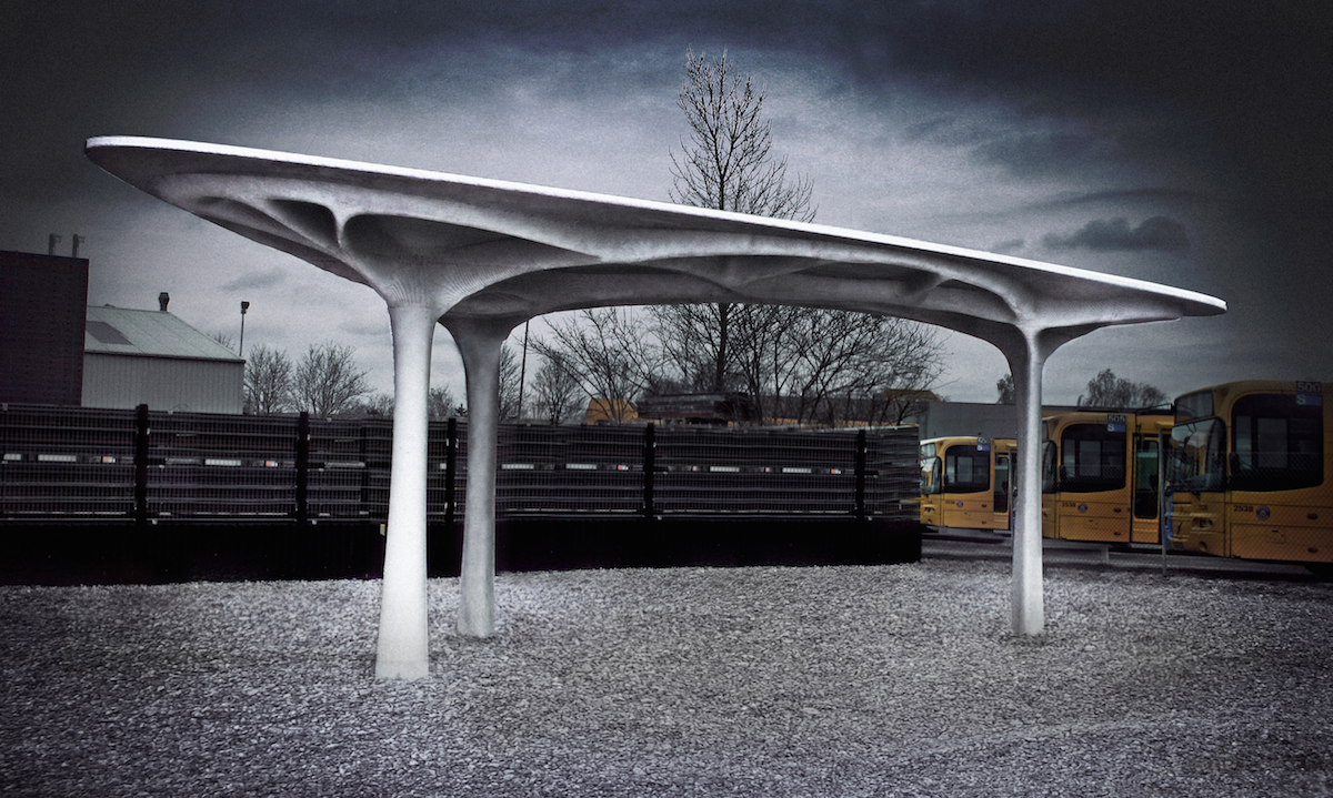
07 – A bus stop built of reinforced concrete and designed utilizing solidThinking Inspire 2014. (image courtesy Aarhus School of Architecture, Denmark. All rights reserved. The school used OptiStruct for the design.)
This real-life finished example is quite a bit different from our bus station roof example shown in the companion product review article (see, “Product Review: solidThinking Inspire 2014,” Architosh, 22 Jan 2015).
To get to a form like this in solidThinking Inspire the designer would establish a design space that approximates the shape of the roof plate and take that volume down the the ground level. (see image 08). Next, random or non-random points for the supports would be chosen. In the above real life bus stop, there are three points for support, visible in the second image below. (image 09).
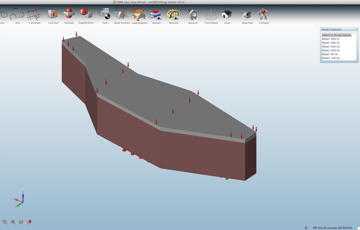
08 – The “design space” volume for the bus stop problem prior to optimization.

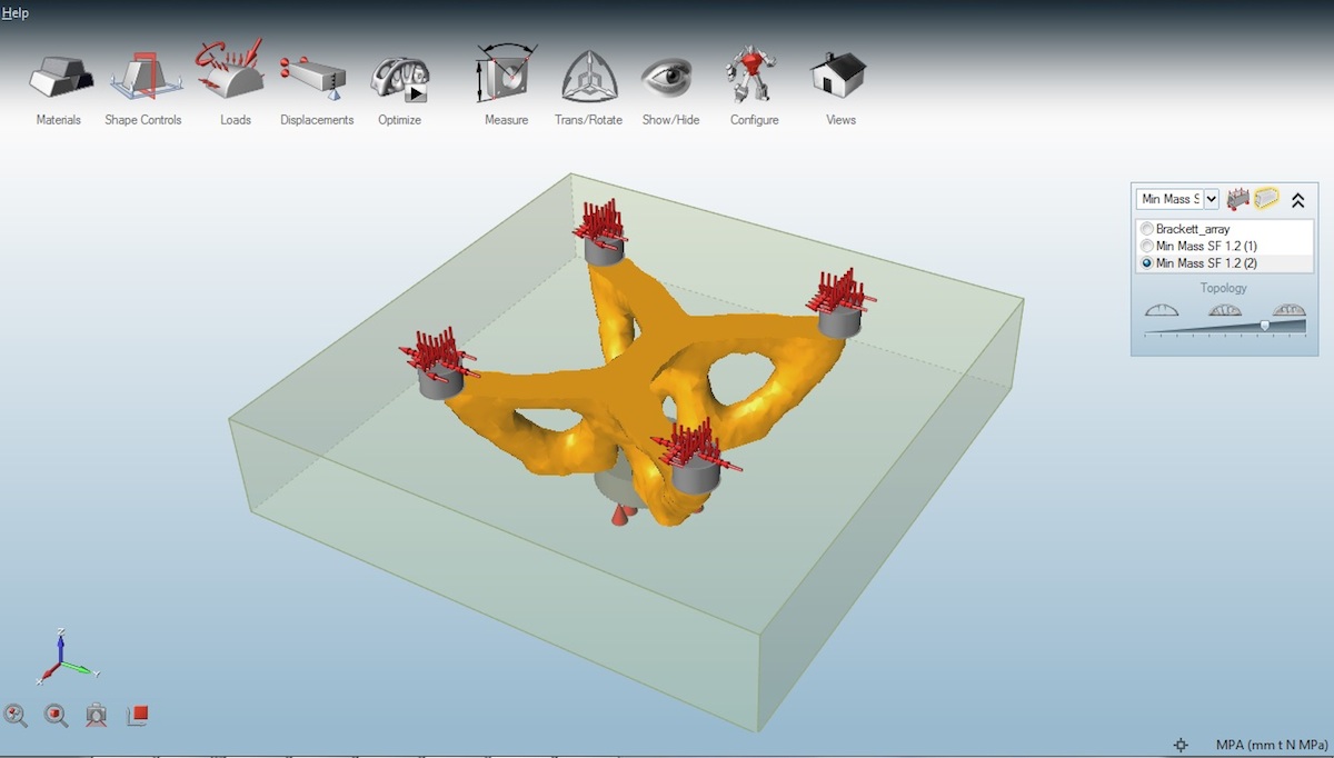
09 – Once a final optimized mass has been run in Inspire an engineer and architect could then take this as a point of departure for further design work.
If you are thinking, “wow, the final built form is so much lighter than the optimized mass model.” (image 09) you are not alone. Inspire doesn’t calculate with materials like concrete or wood. It utilizes mostly metals and plastics, the kinds of materials used in industrial designed products and parts.
If you think about it, one could input a concrete material into Inspire’s materials library; however, real concrete structures utilize steel reinforcing. Asking Inspire to know where it should add in steel to an optimized mass made up of a specific material—concrete in this case—is just asking the program to have artificial intelligence. That would be missing the point. Human design intelligence is what is required next after an optimized mass is created.
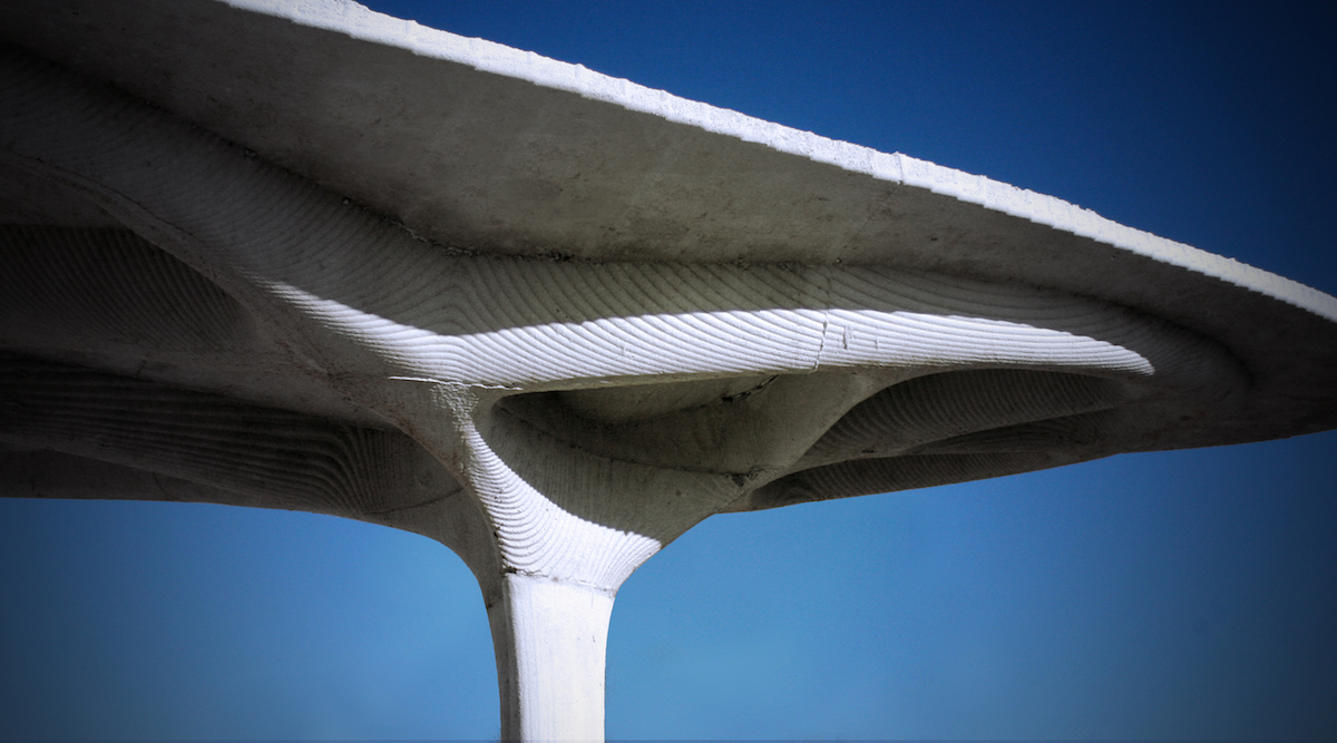
10 – the Inspire based final bus stop structure shown here. (image courtesy Aarhus School of Architecture, Denmark. All rights reserved.)
In the final resulted concrete bus stop, the designer relied on a structural engineer to interpret the optimized mass models generated in Inspire. With reinforced concrete a much visually lighter structure could be created in the final analysis, and it is quite beautiful as you can see in the image above. (see image 10)
Inspire Examples in Architecture
solidThinking Inspire lends itself quite well to generating unique forms and shapes. It is particularly interesting to use for works of civil or architectural engineering where long spans are carried and supports may lend themselves to truss configurations.
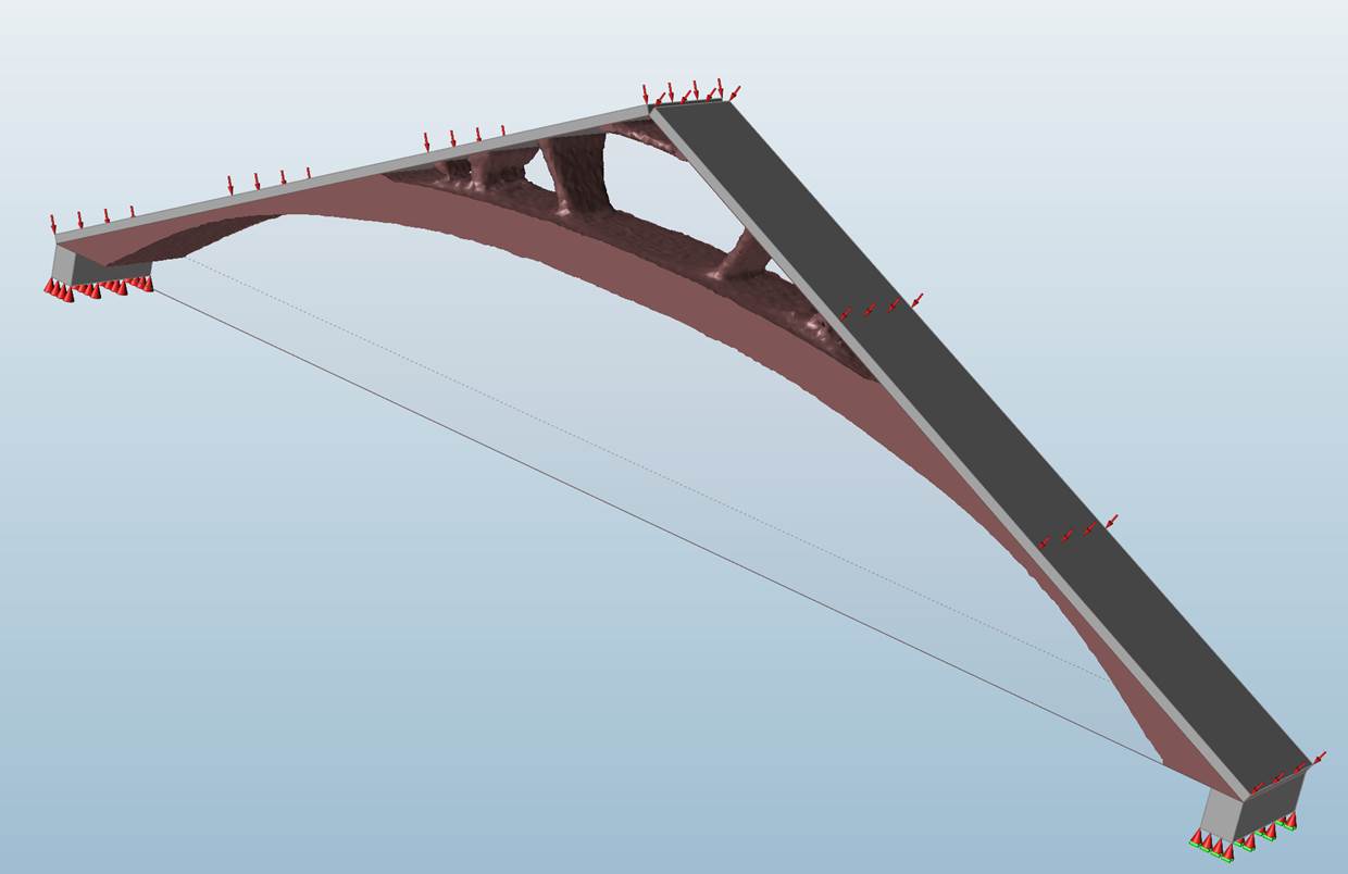
Notice in this video of a bridge structure how similar the support legs look to an animal’s (say dog) legs. There is something beautiful about the generated form and inspiration in terms of how to translate it into structure in steel, wood or concrete.
In the example shown above a bridge-like structure was created and its design space had several deliberately shaped volumes cut out of it. The goal was to force a unique optimized mass that might lend itself to a trussed structure.
As you watch the video notice how at the ends of the structure, there is a very graceful bow that happens to the tall vertical supports coming up to hold the load block (where loading would be envisioned happening at a floor or street level). These support legs look remarkably biomorphic and at least on the right, remind this author of a hind leg on a dog or horse.
next page: Inspire for Architectural Detailing
Inspire for Architectural Detailing
solidThinking Inspire 2014 is also a useful tool for developing architectural details that an architect might qualify as being in a unique class due to various attributes. One attribute could be that there is no particular manufacturer of the architectural part you need in your design or no manufacturer who makes a part you need in a shape or form you desire.
Advertisement
Another problem may be that as an architect you are envisioning a custom system that, as a totality, isn’t even in existence and must be custom manufactured. And finally, while existing parts may be in existence for your building system, as an architect you may simply want to take a weight reduction approach to a new version of an old part.
For the problem defined next, a roof system that bows and is panelized needs to be supported with a quadrant point-loaded bracket. Each bracket bears weight from one corner of four panels coming together about that point. (see image 11)

11 – A paneled curved roof system requires a support bracket that bears weight at four points but itself transfers load at its center.
As you can see in the image above, the bracket space is outlined in yellow as a simple rectangular volume. This will become the “design space.” Once you have created a design space it turns reddish brown in color as shown in image 12 below. The next step is to properly assign loads and forces to the bearing points at top. They support direct vertical loads and lateral loads as indicated by the red arrows. (see image 12 – 13)

12 – The design space now highlighted in reddish brown with shape control planes defined in two directions. .
13 – The optimized mass of the “design space” results in this shape, greatly reduced in mass.
One can also notice that the resultant shape wants to be symmetrical around two axes, so those planes are defined (in reddish tones) in the image above. (see image 12) Next an optimized mass calculation is run and the resultant yellow form is defined. It is dramatically smaller and lighter than the overall “design space” volume in reddish brown. (see image 13)
This optimized shape is then analyzed for stresses and refined in terms of the correct mass required. The designer would then next export the model into a CAD or CAID solution for further design refinement and engineering analysis. In this particular case, solidThinking Evolve was used for the design portion of the next step. (see image 14)
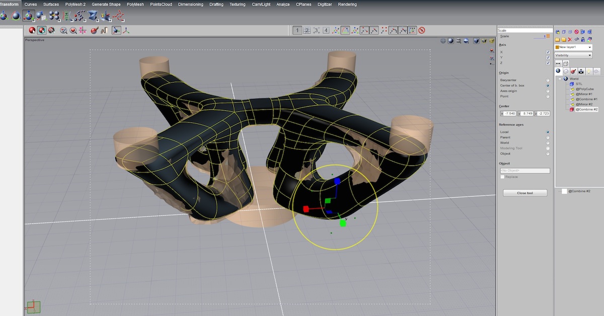
14 – The final model is developed in solidThinking Evolve, the sister product of Inspire.
The final modeling closely aligns with the optimized mass model but is smoothed out and refined for manufacturing requirements.
Closing Thoughts
In closing, it should be much more obvious now how solidThinking Inspire 2014 can apply itself to the work architects do in their discipline. Today’s architecture is developing rapidly due to computerized technology, both at the design stages where architects and engineers create and develop solutions, and also at the construction and manufacturing stages of the building-delivery process.
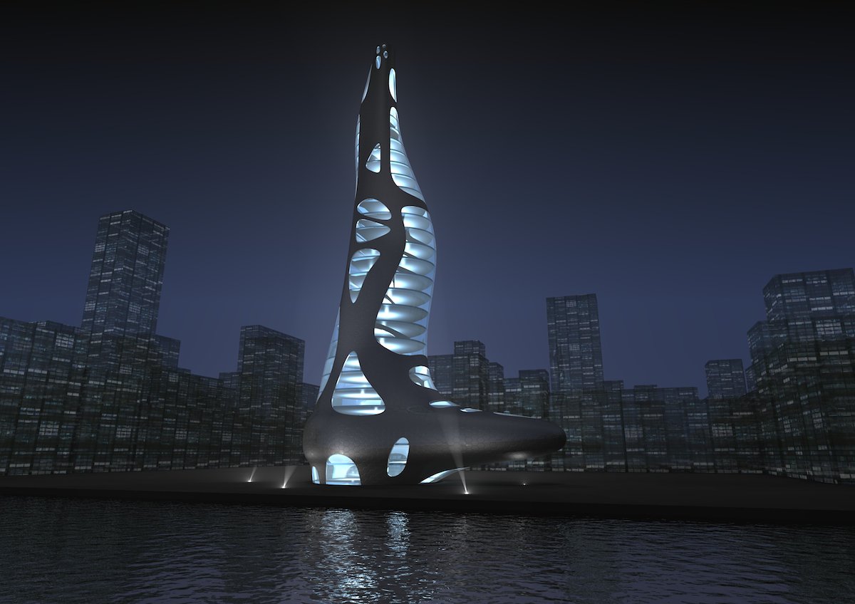
15 – A final images of a skyscraper tower with an innovative facade skin and overall shape form. Typically window to structure ratios are patterned evenly over a skyscraper’s surface, but Inspire can help inform what parts of a tower need more solid structure to resist loads.
Computer-aided engineering (CAE) software technology is advancing rapidly at multiple levels of its execution. While algorithms continue to advance the state of engineering, cloud-based computation resources are making it easier and faster for architects and engineers to run tests, optimizations and simulation, integrating results into the iterative design process.
What Inspire 2014 is offering architects at this time is a mixture of access to some of this CAE technology coming down stream into a design-stage software tool. And with its unique results, architects now have more “visibility” into the structural consequences of their ideas. This visibility is actually liberating and can result in innovation in the field of architecture.