In this feature, the first time this publication has reviewed this particular software, we aim to introduce Inspire 2014 to readers who have an active interest in industrial and product design or architecture and environmental design.
As it turns out, Altair Corporation has some of the world’s leading multi-physics CAE software technology, deployed via an open-architecture, cross-platform set of solutions. HyperWorks, now at version 13, is the hub product of those solutions and runs on Windows and Mac and features a series of “solver” solutions. One of the key solver solutions is OptiStruct, an award-winning conceptual design and structural optimization technology. It’s this technology that is closely tied to the unique features of solidThinking Inspire 2014.
Introduction
When we originally set out to review this product the aim was to focus specifically on the exploratory architectural aspects of its use. However, as luck would have it, our review grew too large. Therefore, we decided to publish a general review with a companion special feature article on the use of Inspire 2014 for generative and conceptual architectural and civil design. (article coming in a few days). It’s important to expand the notion of this tool beyond architecture. As you will see, both here and in the special companion article, Inspire has wide applicability to structures of all types.
This review will contain three main parts. Part 1 will detail the features that are new to solidThinking Inspire 2014 and cover the general workflow within the program. Part 2 will then take the reader through some sample problems to familiarize the reader with the nature of the program. Finally, Part 3 will briefly touch on the architectural aspects of the program and offer conclusions. The companion feature will delver deeper into the architectural nature of the program through case studies of how to use Inspire 2014 to ideate, to generate inspiration, and even to solve particular real-life workflow challenges.
Part 1: New in Inspire 2014 and General Workflow
solidThinking Inspire 2014 gained more power in this release in the areas of computational analysis germane to the nature of the program. More specifically, more solver technology is onboard Inspire 2014 than in previous versions. Here is a brief run-down:
- Linear Static Analysis — You can now run linear static and “normal modes analysis” on your model. Architects will be familiar with the concept of linear static analysis on structures but normal modes analysis is less familiar to them.
- Geometry Simplification Tools — Less important for architects than mechanical and industrial designers, these new Simplify/Patch tools help clean-up areas in the geometry prior to establishing the key “design space” required for the analysis and mass optimization. With it you can remove holes, rounds, fillets, et cetera.
- Concentrated mass parts — are used to account for the mass of a part when running an optimization using frequency constraints or when analyzing for normal modes.
- Smoothing options — used for smoothing the optimized mass in preparation to sending it out to other programs for refinement modeling and design.
A significant change in Inspire 2014 is that you can now make new parts from solids. Coming from more of the architectural world, this author found this tool quite familiar and different at the same time. The push/pull modeling tools in Inspire 2014 are really quite nice. And they work particularly well in conjunction with the way in which one orbits, pans and zooms the model. (see image 01)
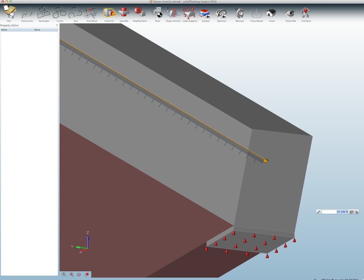
01 – Inspire 2014’s Push-Pull tools have a nice feel and features for accuracy, affordances, and ease-of-use.
It won’t be possible to create very complex massing models for your parts in Inspire 2014 and that’s actually a good thing. It turns out that when it comes time to optimizing parts and structures for minimizing mass, the “design space,” which you use and we’ll discuss in a minute, benefits from simplicity. It may be common for users to struggle with this general idea, perhaps more so if they are in the architectural world as this author is. What happens when parts are too complex is that the optimizations either fail or simply take too long to run.
Advertisement
There are definitely cases where particular shapes, that are not necessarily too complex to be good candidate “design spaces,” will need to be generated in other CAD software. This is fine. We brought in several test models. Inspire can bring in models from all the major MCAD players and also open industry standards like IGES as well as geometry kernel file types such as ACIS and Parasolid. This means architectural tools are also very well suited to sending models to Inspire 2014.
In fact, this is why there are the geometry simplification tools. If you have designed a part prior and now want to see how to evolve that design part so that you can reduce its weight while making it stronger, simply bring that model into Inspire 2014 and clean it up using the geometry simplification tools.
General Workflow
Before we launch into explaining how one works in Inspire a quick word or two about the program’s general environment is due. solidThinking Inspire 2014 doesn’t share the same UI as solidThinking Evolve, another program we have recently produced a feature on. For those who have read our feature on Evolve you may notice this immediately from the screenshots below.
MORE: solidThinking Evolve for Architectural Design Modeling – Part 1
Inspire’s technology, while related to solidThinking Evolve, was fully developed by Altair Engineering. The two products share the same “solidThinking” brand name but their program origins are quite different. And so are their user-interfaces. I bring up solidThinking Evolve because it is germane to the discussion of the workflow in Inspire.

02 – Inspire 2014’s user-interface, toolbar at top features intuitive icons, with property editor to the left where edits can be input on values. A sample beam problem is shown above.
The general idea is that a product or industrial designer would sketch out ideas and bring those rough ideas into Inspire. Knowing how the product is meant to function and what forces it must deal with, including gravity, the part or product would go through a mass optimization process whereby Inspire generates an “optimized mass” and often organic-looking revised part. This more organic result is meant to inspire the designer and not necessarily be taken literally. Rough structural analysis of the part or product can be run in Inspire, further informing the designer and his or her process. That specific information can be shared with product engineering or in the case of civil or architectural design with a civil or structural engineer.
With engineering input, a further iteration may take place again through Inspire or the resultant work may move onto another program for further evolution, such as solidThinking Evolve. This is the general Inspire workflow.
next page: Part 2: Sample Problems and Workflow
Part 2: Sample Problems and Workflow
One of the most important concepts in solidThinking Inspire is the concept of the “design space.” This is the three dimensional volume form or space in which mass optimization takes place. (see image 03). An individual volume is assigned as the “design space” and this turns that volume a reddish brown. When optimizations are run on this design space, after loads and supports are set in place, Inspire 2014 produces an optimized mass for that part or section of a part assembly. (see image 04).
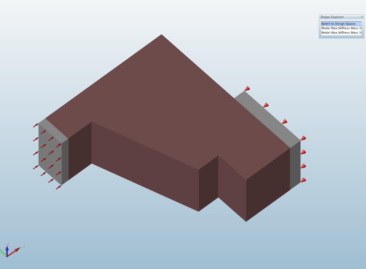
03 – In Inspire 2014 you establish the “design space”, the volume from which mass optimization takes place.
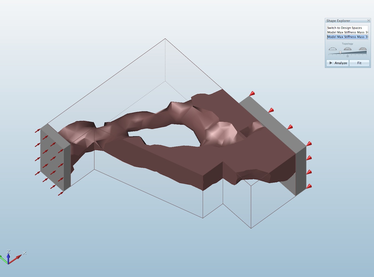
04 – The design space is now shown in outline with the “optimized mass” part remaining.
The design space is the volume from which mass optimizations occur but analysis takes place across the entire assembly of model connected to the design space. In terms of how one works in the program, generally, between operations one hits the escape key or right clicks on the mouse to exist specific tools and procedures in order to then choose new tools and procedures. The video below shows the the nature of creating a “design space” as well as demonstrate the push/pull modeling tools.
The video above shows how quick it is to create a “design space” with a basic shape. We learned during the review that the simpler you can make the design space the faster optimizations would run. This makes sense, naturally, but was not obvious at first.
One thing that is very important to note about Inspire 2014 is that design spaces should be not very complicated, they should be simple volumes. The more complicated a design space is the more time it takes to run an optimization process. This is very important because Inspire doesn’t support the ability to work on more than one model at a time. So while optimizations run in the background, you can’t load another model in the foreground and work on it as another optimization runs in the background.
A Beam Problem: Design Spaces, Analysis and Optimization
A more complete sample problem is really in order here but this time we’ll cast the problem in basic architectural terms and conceptually study a simple beam. We realize folks are not interested in Inspire so they can design beams, and even if you were this is not the program for that. However, a beam is a basic structural concept architects will understand. Additionally, architects will also be looking for a result that meets the expectations of their training.
The beam volume is established as the “design space” (shown in reddish brown). It sits on columns, which are not part of the design space, and supports are positioned at the base of these columns. Prior to optimization, a quick analysis test was run and results are shown in the images below (04 – 06). As you also see displacement maxes out at the beam’s top edge as the supports are at the column bases. If the columns were shorter—and therefore closer to the design space carrying the loads—the displacement would be smaller.
05 – basic beam problem defined with beam volume as “design space”
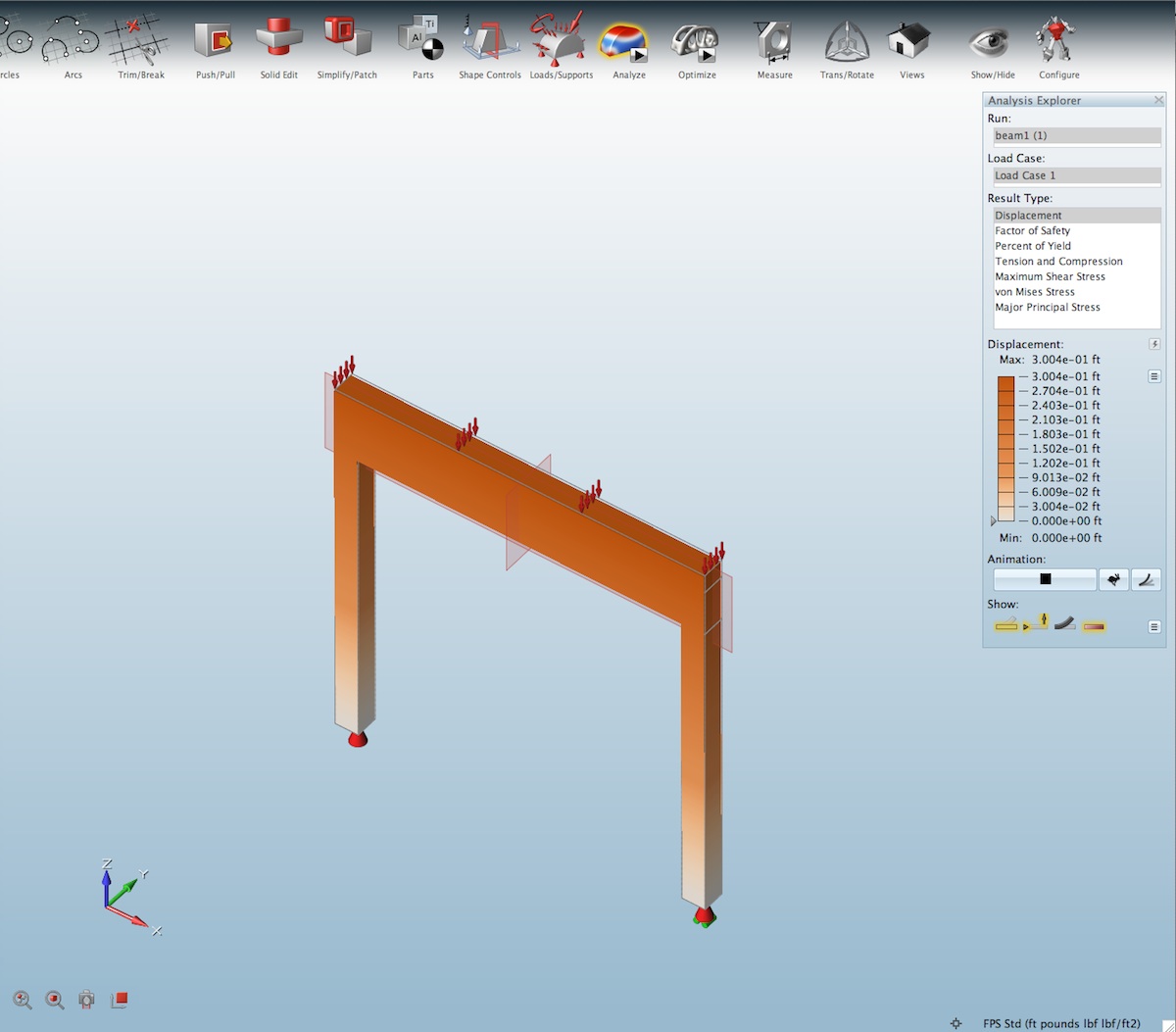
06 – in this analysis of the design space without optimization we see the displacement.
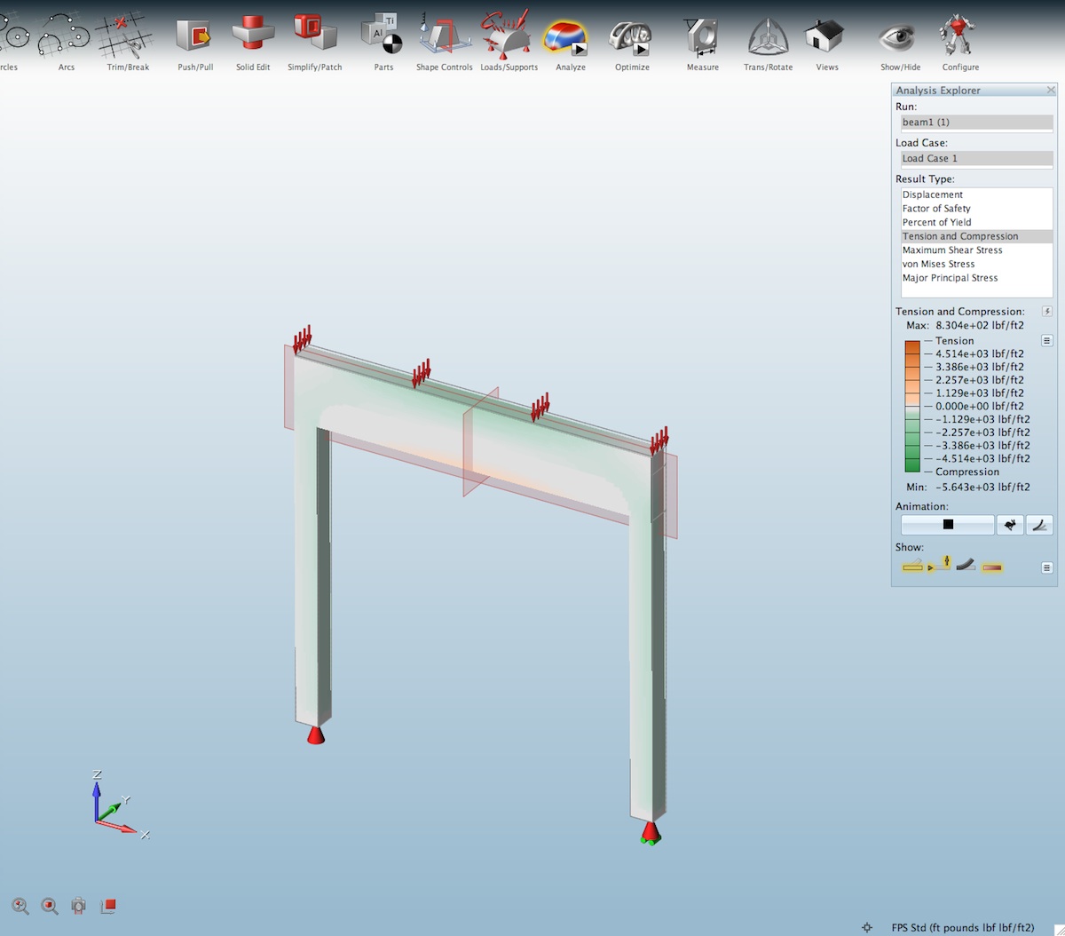
07 – beam analysis, compression and tension.
One reason we start with a beam is because architects understand how such structural members respond to loads. An even distributed load is going to cause a maximum deflection of the beam at its center. Unsupported laterally, we can also examine how the stresses (forces) move the structure as a “design space” and this should intuit in the architect or industrial designer what ways the structural package can be developed to resist the forces applied to it, as well as what is likely necessary in the surrounding elements about the design space. (see image 05 for displacement, which runs perpendicular to the beam’s length).
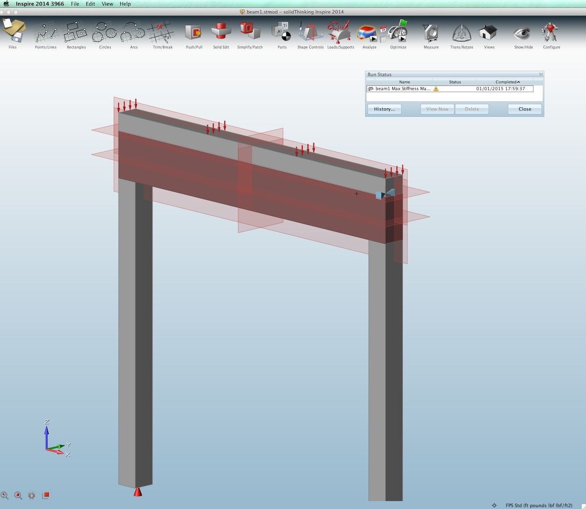
Next we run the mass optimization. In both the running of analysis and optimization we hit the “play” button on the icon in the toolbar. (see image 08)
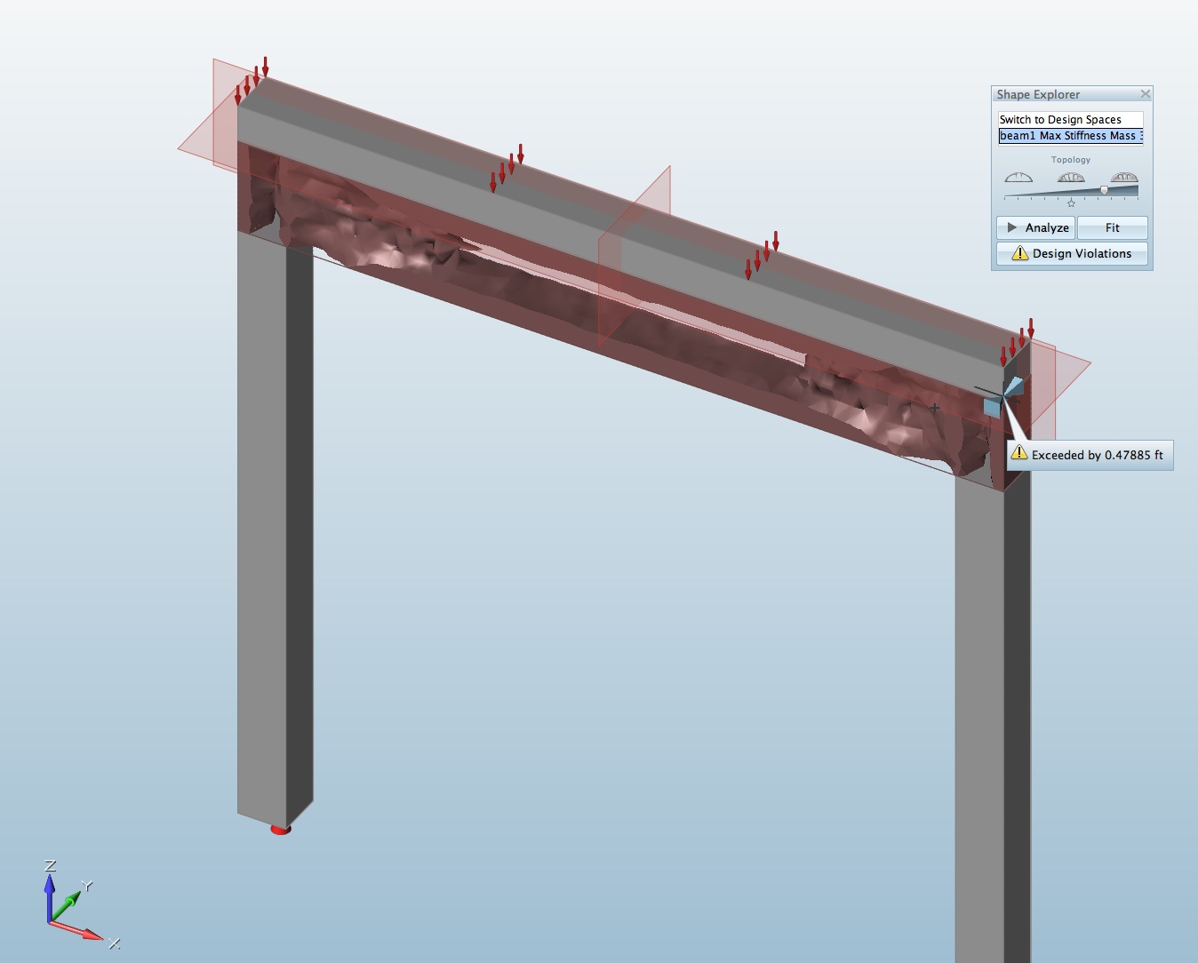
08 – Beam problem, mass optimization view showing the “design space” now minimized to the location of mass what is needed to resist forces (loads) on design space.
Our mass target was the default 30 percent of the design space. A slider presents itself in the Shape Explorer palette, with icons that indicate minimum and maximum mass targets. You can also toggle back and forth between the optimized mass view and the design space itself. (see image 08 above). In the view above we slid the mass slider up towards more mass in order to connect all masses with the design space volume. This is critical for analysis runs on the optimized mass, which is what you do next by hitting the Analyze button in the Shape Explorer. (see image 08 above and result in image 09 below).
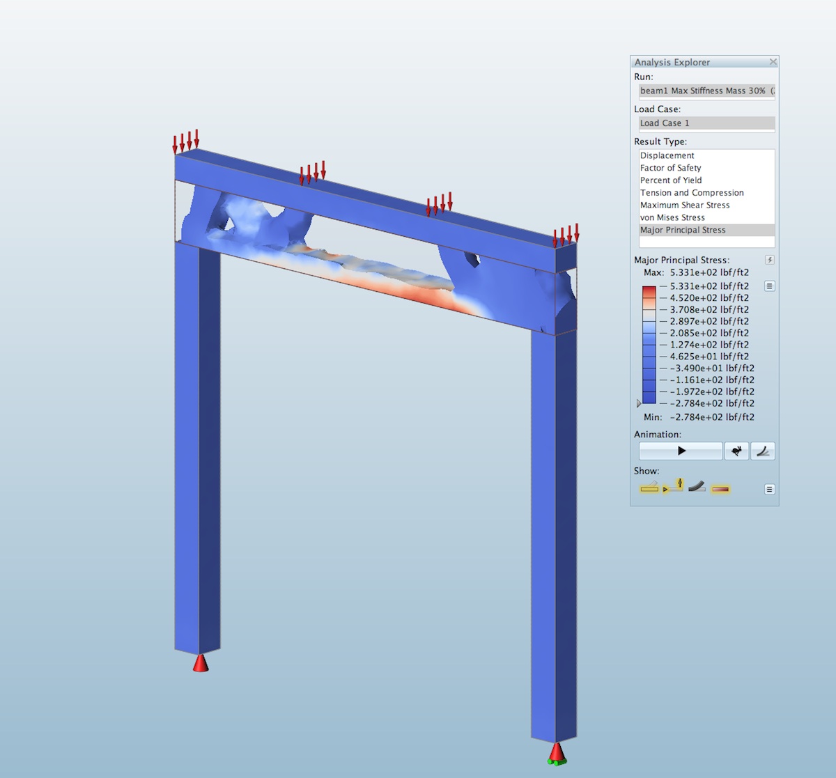
09 – the beam’s optimized mass is now show under analysis, showing max. stress in this view.
A few things to point out. If you were expecting a wide-flange beam shape clearly we don’t quite have that. But it’s not far off. What is in affect happening above is that the load block (in grey) is acting like the top flange and the mass between (top and bottom) is thinned out, particularly at its center. As you can see above, architects already know that the top of the beam is in maximum compression while the bottom center section is in maximum tension, indicated in red in the analyze view (image 09). Directly in the middle there is zero tension or compression at a particular point, in other words zero forces. This partly explains why there is air in the direct middle—mass is not needed there because no forces transfer through that section and hence you don’t need mass. In real steel beams, of course, we have a consistent web across the main body of the beam for manufacturing reasons.
Let’s move on to more fun activities in Inspire 2014 by exploring quickly, some architectural forms and some of the visualization aspects of the program that make this tool really interesting to work with.
next page: Part 3: Introduction to Architectural Exploration with Inspire 2014
Part 3: Introduction to Architectural Exploration with Inspire 2014
For some readers this section is the entire part of the feature you have been waiting for. Developing more complex architectural studies with Inspire 2014 takes investment in learning the nuances of the program. While the examples shown in solidThinking’s literature are quite amazing, getting to such results yourself requires understanding the program’s limitations and subtleties.
Advertisement
We have an entire dedicated in-depth companion feature devoted to this subject where we show some amazing things others are doing as well as work through several case studies demonstrating the use of the program in architectural workflows.
Bus Station Roof Study
In our first efforts we looked at creating a roof structure for a bus station, or some such structure. Supports are from the center while a larger roof cantilevers both sides. A “design space” (shown in reddish brown) is given an approximate shape. Next, a continuous block for support is set under the entire middle support section. One could think of this as the foundation. (see image 10)
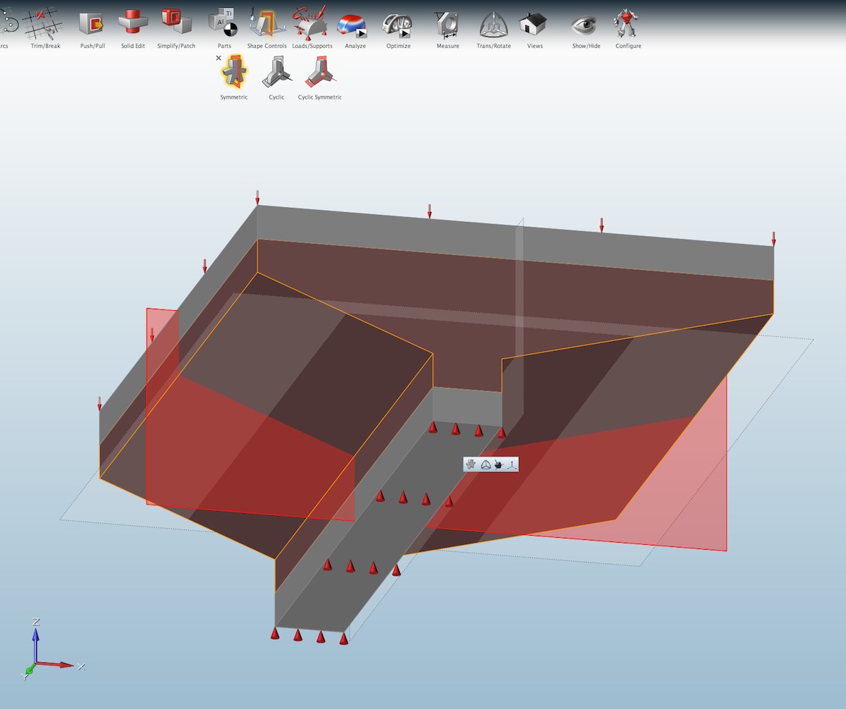
10 – A roof structure for a bus station. Defining the basic shapes, loads and supports.
The next element is the roof which is shown simply as a loaded, rectangular mass. After placing supports at the bottom element, placing loads on the roof element, and defining the shape controls (red planes) a mass optimization run is begun. The result is generated within 10 minutes. Importantly, we should review the optimization palette and share some tips.
The optimization palette includes some important settings and two fundamental objectives. You can either optimize around maximum stiffness or around minimal mass. The image below shows the maximum stiffness option with mass targets indicated at 30 percent of the design space volume. (see image 11)
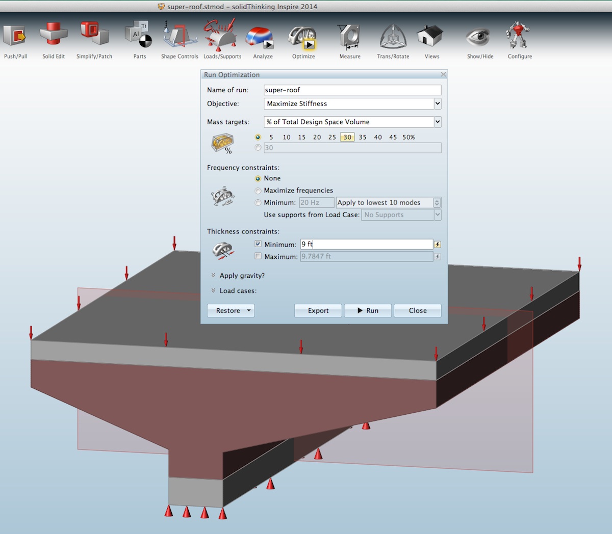
11 – The optimization palette continues two fundamental options, designing for maximum stiffness or minimum mass.
A key discovery during the review process was that the minimum thickness constraint value was often too little. As a result Inspire 2014 would often take far too long to calculate the results or not complete them at all. The tip came from the folks at solidThinking that Inspire considers every model element—not just the “design space” in its minimum thickness constraint. It was therefore suggested to raise the default values that appear in the input field, making sure that no model element, outside the design space, has a thickness smaller than the “minimum thickness” across its key dimensions. This dramatically improved optimization run times, and greatly sped up the review process itself.
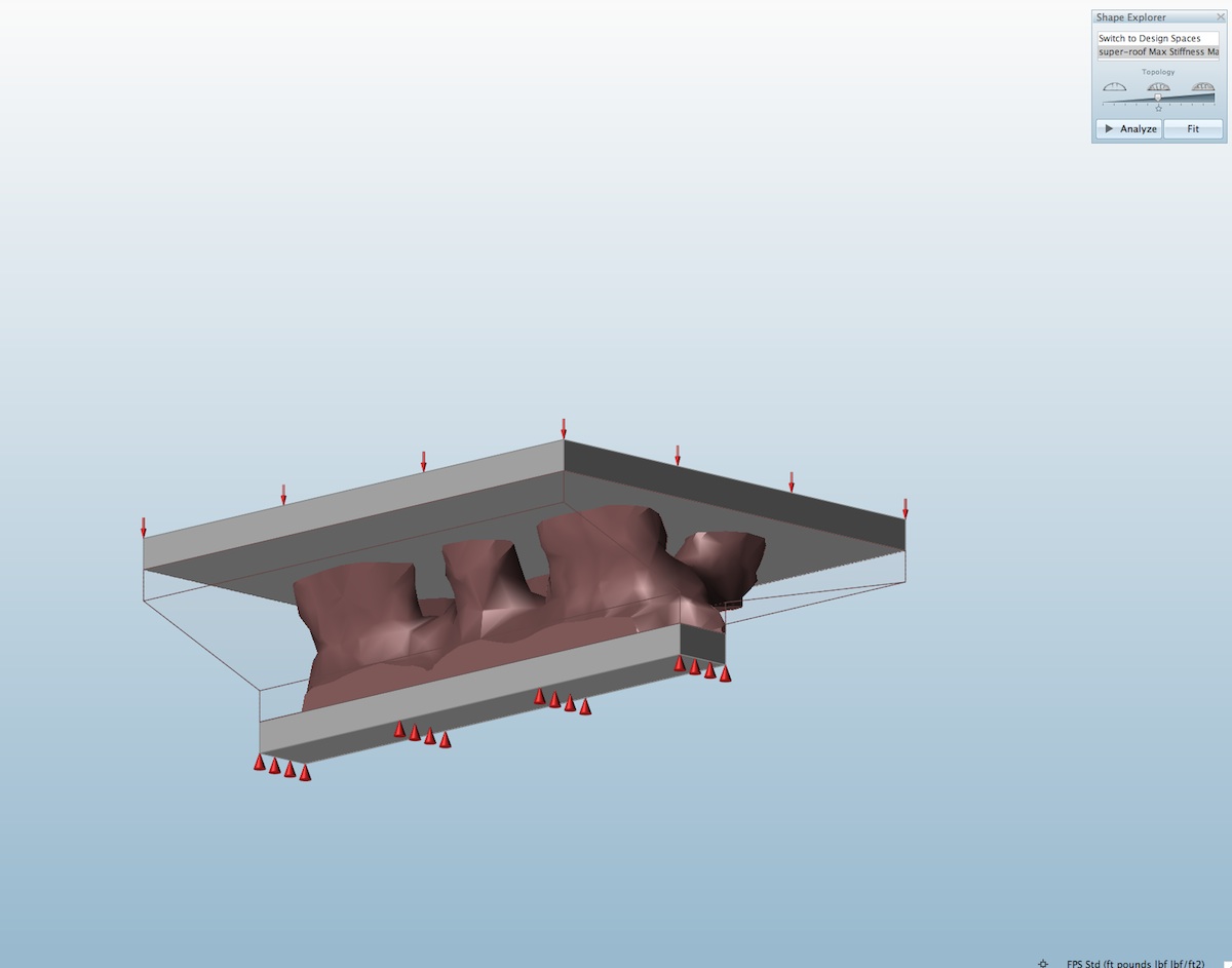
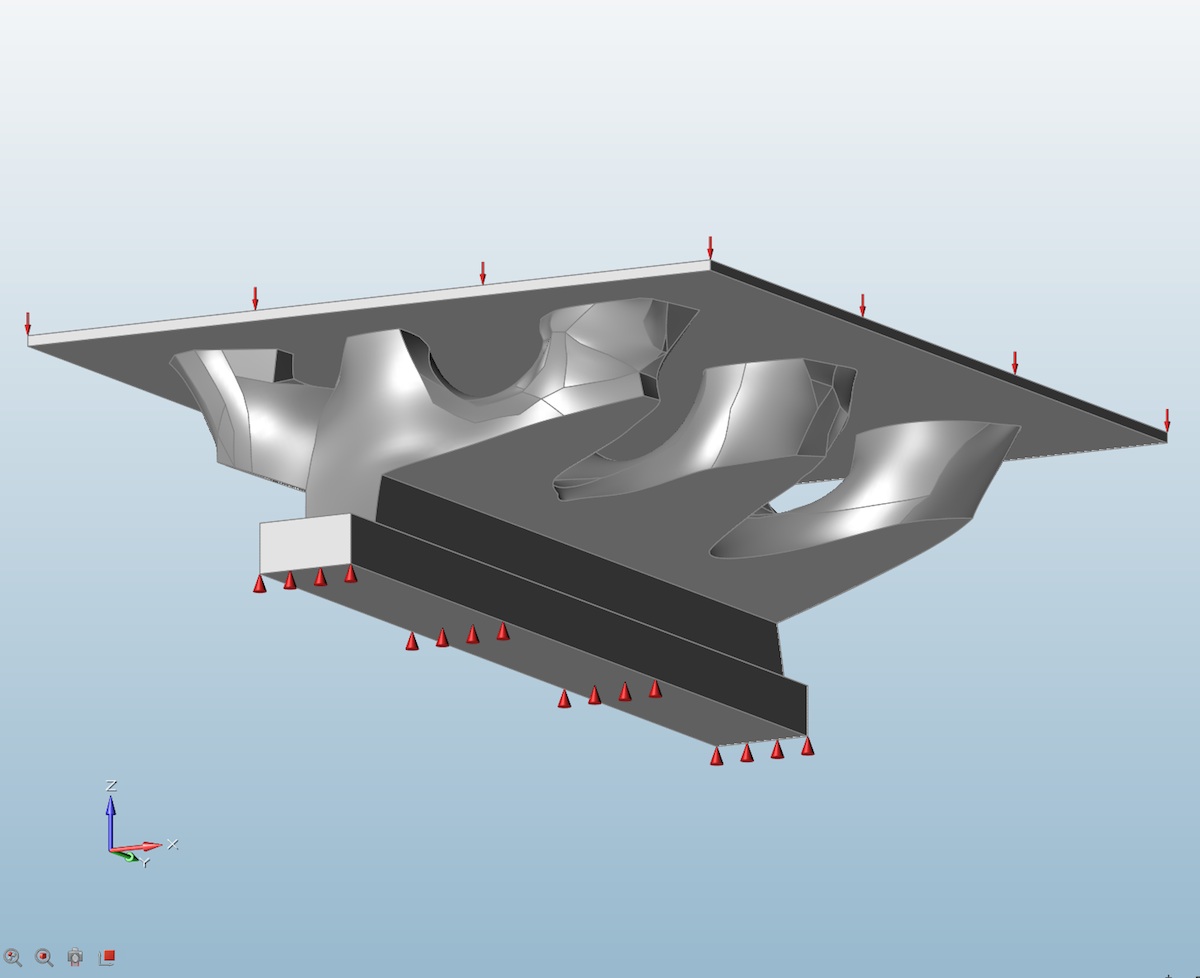
12 – The optimized result with the first set of values.
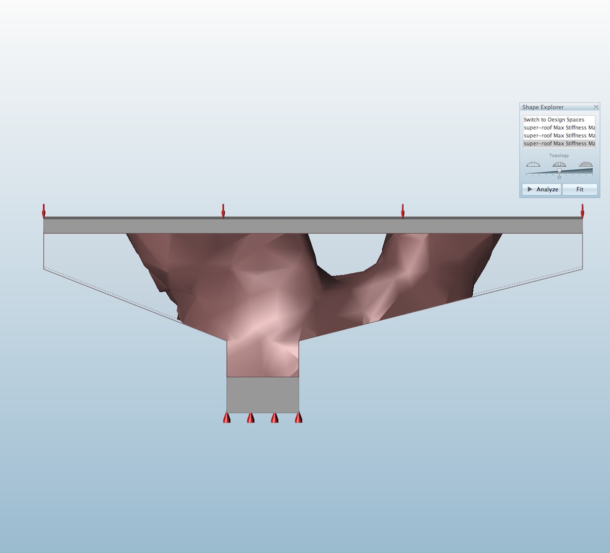
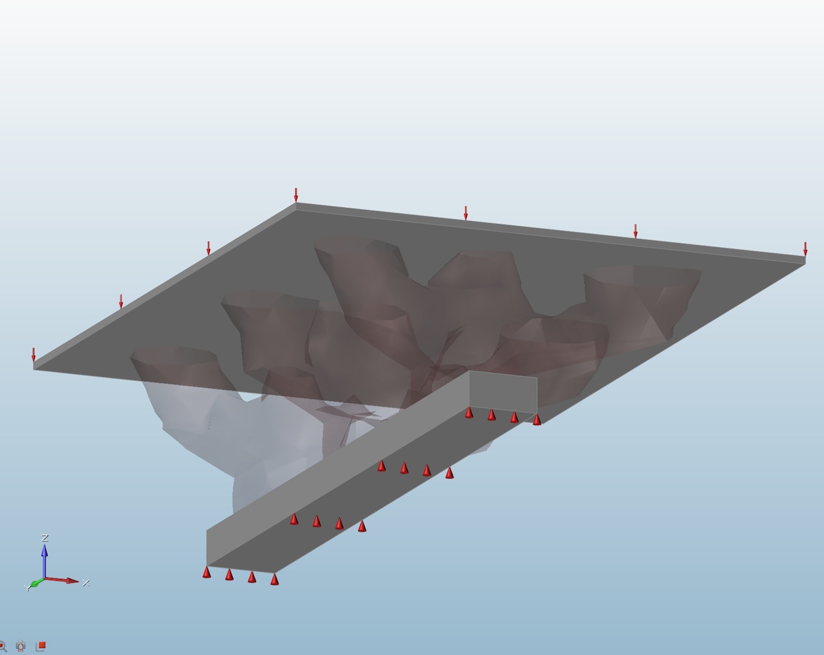
13 – The side view shows that when we thin the load block above the design space the optimization pushes mass further out to the edges of the design space, due to the decreased self-support in the load block itself.
Above you can see a series of images showing the mass created by the optimization. Note that the entire structure consist of mass elements (blocks) of solid steel. Inspire allows the user to choose other material options, such as aluminum, titanium, plastic and so forth. The top grey element has the load applied to it. Given its initial thickness, the extent to which the organic shaped structural mass that needed to reach out to support its edges was minimal. When we reduced the thickness of the roof load block, the optimized mass changed and reached out further to the roof’s edges. (images 11 – 12). Again, think of the shapes being shown and note that, like in the beam problem above, the top load block begins to participate in the resultant structural forms like a top flange.
Unlike the beam problem however, the load block can only be so thin before it itself causes massive displacement due to the forces. This is why Inspire has its name. The resultant shapes are meant to inspire the creative process, not dictate structure and structural arrangement. The roof on the bus shelter structure above might wish to be light trusses itself running perpendicular to the view or a heavy metal and concrete composite deck that can span web-like truss structures in steel that reflect the shape of the minimized mass.
In the video below you can see the deflection and displacement of the resultant “optimized mass” and this video is very informative for any designer and engineer.
The video above shows the displacement and tension versus compression on the optimized mass for the bus station roof structure.
As you can see from the images below the asymmetry of the design causes unequal displacement. The user can explore multiple runs with increases and decreases of the roof load block and thicker optimized mass for the design space.
Another view below shows the semi-transparent function available in Inspire, which looks a lot like x-rays, which you will see more of in the companion architectural feature on Inspire 2014. (see image 14)
14 – A semi-transparent view of the result optimized mass.
15 – Inspire 2014 now features a smoothing function that smooths out the organic, generated optimized mass model.
One of the key goals with using Inspire 2014 for architecture is to find interesting structural forms. Some readers may be wondering about the use of concrete as a structural material. Can you use it? The short answer is no. Certain types of materials, like wood and concrete, don’t offer the right physical properties that lend themselves to the solvers in Inspire 2014. We will discuss this in more detail in the companion feature.
Looking at the Possible
In this brief look at a bus shelter roof type of problem we were able to generate an interesting set of forms and options. The next logical step after this type of work is to then take the smoothed model out (export out) to another CAD modeling tool and create more refined geometry that responds to the lessons inherent in the optimized massing model.
At that point the work down in Inspire may end for architectural objectives. While, in product and parts design, another iteration may likely take place. The analysis tool works fully on final resolved design forms, checking for all the same stresses that are run on “optimized mass” parts. This iterative process can be quite detailed but Inspire 2014 has the ability in such analysis to assign various constraints like displacement, frequency, and stress. If you notice at the beam problem (image 08), a displacement constraint was exceeded during the run. This informs the designer that the design goals are not working and to revise the work.
We have a lot of interesting work to show you that was done in the areas of architectural form exploration, using Inspire 2014. In the first image below we show some teaser work on an bridge, platform or dock structure whose supports were far below the level of the even load it carried. Think bridge design, for example. (see image 16)
16 – An architectural example problem.
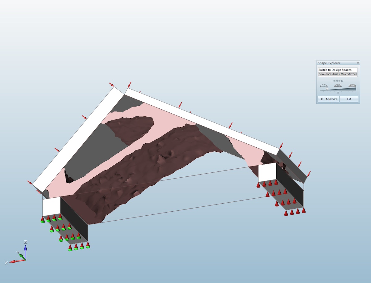
17 – Another architectural sample problem.
In the next example a simple un-equal roof shape is caring unequal loads, resulting in an asymmetrical optimized mass. Again, like the basic beam problem, the loads are applied to a load block which, being made of steel, in the end must be read as part of the structure. In this case, the top chords of a truss form. (see image 17)
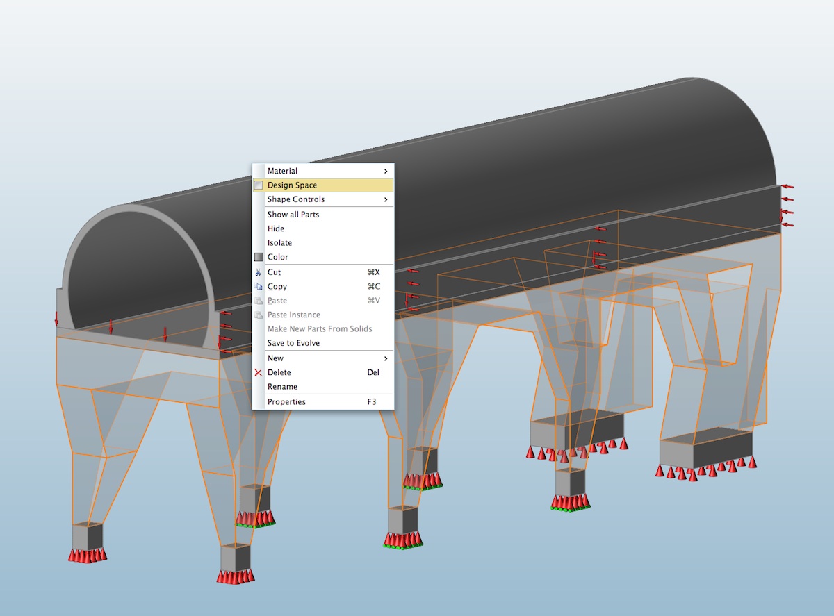
In the final image below, a fully developed architectural concept that has been taken through advanced iterations in Inspire 2014 shows an organic form holding up a futuristic linear structure high above the ground. (see image 18)
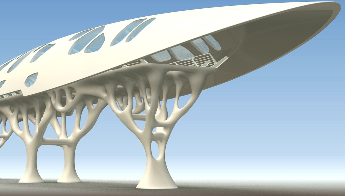
18 – An fully developed architectural concept. (image: courtesy of solidThinking Inc. All rights reserved.)
This is an example of what can be generated with a combination of the Inspire and Evolve solidThinking software toolkits, with or without combinatory efforts in other CAD tools.
Conclusions and Recommendations
solidThinking Inspire is a truly unique tool and in a class by itself. The program acts as a hub for computer-aided engineering (CAE) type analysis brought to the front-end of the design process. In the architecture space, the innovation in Inspire aligns well with the trend in what some call “front-ending” the analysis. Given the rising importance of our environment in the face of global emissions and the push for more sustainable buildings, key innovations in architectural software have primarily focused on testing the energy consumption of structures earlier in the design phase—i.e.: bring analysis to the front end of the design process where bigger impacts can be made.
Advertisement
Inspire 2014 helps designers make parts, products and assemblies better by addressing the strength versus weight ratio. For architectural work, the company has expressed the product’s value a bit differently, focusing on finding innovative (and yes! lighter weight too) structural forms. To be perfectly honest, Inspire 2014’s help and literature is mostly aimed at product and industrial designers, not architects.
To make this very good product even better there are some low-hanging fruit to address. An on-boarding process for the architectural professional in terms of what does it mean to focus on workflows that eliminate weight in building mass? What types of problems at what scales can be addressed? How do they get setup in the software? This would be a good start.
Functionally, Inspire doesn’t allow you to open multiple model windows at the same time. So you can’t be working on two problems at once in discreet windows. It would be nice too if there was a way to distribute runs (optimization and analysis calculations) across multiple computers, a la, render farm style. Anything to speed up design iteration. And speaking of iteration, a side-by-side ability so a designer can compare two closely developed solutions might also be useful.
In the final analysis, any product or industrial designer seriously interested in minimizing weight while retaining strength objectives will find real job and useful results in Inspire 2014. The tool is also simply fun to explore and play with, making the design process quite engaging. That’s one of the reasons why architects in particular might find using it deeply rewarding over time—it sponsors curiosity in the user in a way that engages design thinking. —- ANTHONY FRAUSTO-ROBLEDO, AIA, LEED AP, Editor
Pros: Despite the sophistication behind the technology, the user-interface is remarkably intuitive and easy to engage; excellent new solver technology helps designers explore deeper analysis; good improvements to modeling features in refined push/pull tools, new sketch plane features and new parts from solids are all excellent—the program is a pleasure to model quickly in; reliable Boolean tools and good new improvements in tool groupings in the toolbar; new smoothing feature and ability to explore out to other CAD tools; superb tutorial and help tools with text and video.
Cons: there needs to be more information to provided to help those in architecture work with the software; it’s not possible to work on two problems at once in discreet workspaces despite runs that work in the background; the program reports in OS X Force Quit dialog as being “non-responsive” in the early stages of some optimizations, when in fact the program is not hung.
Advise: A truly engaging tool that most product and industrial designers would benefit from having in their arsenal. Various classes of architects may find a healthy range of objectives to be solved by Inspire. The technology has great promise for the architecture and architectural engineering industry by bringing more analysis work to the front end of the design process.
Cost: Inspire 2014 starts at 5,995.euro or 7,995.USD.
![]()

SaveSave