In the early part of the summer we had a chance to sit down over a webcast with the solidThinking folks about their products–what at this point include two: solidThinking Evolve and solidThinking Inspire, both now at version 9.5. The purpose of this first sit-down was to allow us to get much more familiar with how one works directly in solidThinking and in Evolve in particular.
Advertisement
solidThinking, Inc., has extensive far-reaching plans for the evolution of this software–one of the premier product styling or computer-aided industrial design (CAID) programs in the world and one of a few limited products in this league that runs on the Mac. Of course we wanted to talk with them about that. If you recall our AIA Denver reports Altair–solidThinking’s parent company–was at the show primarily showing off technology squarely aimed at the architecture market but utilizing FEA and other engineering technology. But what about solidThinking itself? Well, Altair wasn’t really focused on showing that at the AIA show though they did have it on display as a second cast member. That is not to say they don’t see solidThinking as serving the architecture market–they do. But while it is already utilized it is not the product’s primary focus market. That market is industrial design.
Today’s Most Advanced Architectural Buildings Are Not Unlike Industrial Products
From our view we see the merging of modeling technologies impacting both MCAD and AEC CAD markets as having several common themes and technology thrusts. Firstly there is the direct-modeling (explicit modeling) movement afoot in the MCAD space. Secondly there is the further parametrization and associativity progress being made with BIM. Also, there is the focus with architectural modelers to enable them to not only get more associative but to include features that act a bit like “deformers” that can reshape entire sequences of modeling elements with one quick maneuver.
The subtitle’s implicit argument above is not new. Frank Gehry has been using an aerospace industry CAD product (CATIA) for over a decade and built a second company around it in Gehry Technologies‘ Digital Project. If software for designing jets can be useful and specifically beneficial for Gehry’s architectural creations, might software created for designing industrial products like coffee makers and sailing boats also be useful to creating architecture?
The short answer is “increasingly yes.”
Indeed solidThinking Evolve and Inspire both have fruitful impacts on the AEC space. Yet our thinking lately has been keenly interested in solidThinking’s industry-leading Construction Tree history capabilities and specifically how beneficial such technology could be for iterative work in architecture. Especially at the conceptual and design development stages.
Getting Familiar with solidThinking
Today in this feature we will begin to touch on conceptual architectural modeling in solidThinking a tiny bit. That is not the primary focus for this article. This feature is about getting familiar with Evolve’s modeling prowess in general, which will be a multi-article process as we delve into everything there is to know about solidThinking.
solidThinking’s strength is in the area of surface modeling (curved or organic surfaces) with parametric control and editing and the ability to scale those surfaces. Tony Norton, of solidThinking set me up with his European colleague Adel Matar, who is a solidThinking expert, to show me some of Evolve’s modeling capabilities.
The Chair
Adel starting by drawing just two primary elements. The first was a primary shape which he extruded to form the back of the chair. This was a NURBS curved element. The second element was the trim curve, a spline or NURBS based curve, in 3D space that defines the top edge of the chair in 3D. This second trim element is just as important as the primary initial shape for the chair in the final design because one can keep going back to it and redoing the curve to give the final chair design a new shape. (see images 01 – 02)
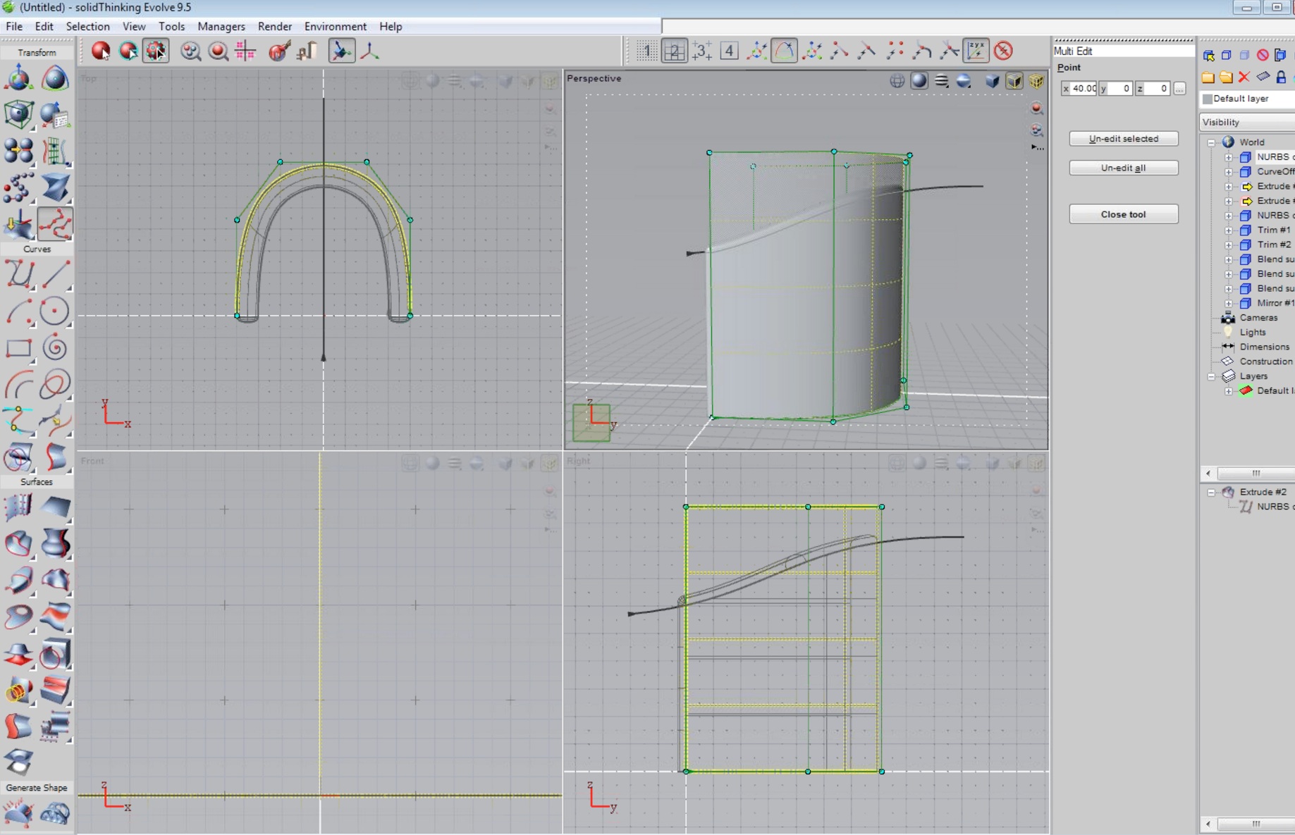
01 – The chair consist primarily of two elements, both NURBS curved based and parametrically controlled.
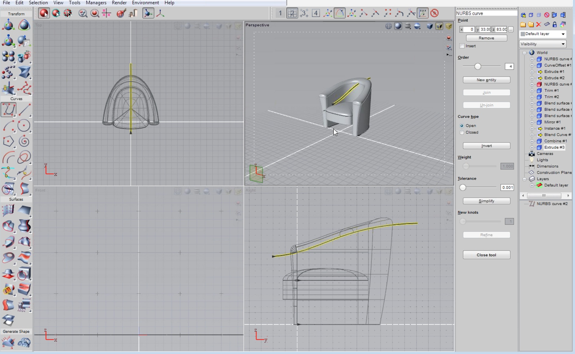
02 – The second curve is used for clipping the top of the chair and giving it its slope and overall definition.
With solidThinking Evolve 9.5 it is quick to get to this level of design with just focusing on two essential elements as discussed above. The primary NURBS curve gained a thickness early in its definition. That thickness is a parameter that can be edited at any time. The curve itself and the vertices that make it up too are also editable by simply select highlighting and altering. The curve can be redrawn a thousand different ways with numerical input finesse if desired. And of course the clipping curve gives the chair its critical design slope.
There are of course other things that need to take place in the design of this club chair. One is the caps or flat ends of sections like the chair top or arm. Those faces get curved quickly with numerical control in the dialog boxes using the Round command. Another key aspect to designing industrial products like furniture is handling the blending of surfaces. solidThinking Evolve does this very well with a large degree of control options.
In our example shown below the two surfaces defining the caps are set to match each other. There are controls that enable the tangent planes to be inverted (both, one or neither), options for following surface isoparms on either surface one or surface two or allow for direct UV editing as well as handling smoothness in absolute or scaling terms and an overall quality setting slider. (see image 03)
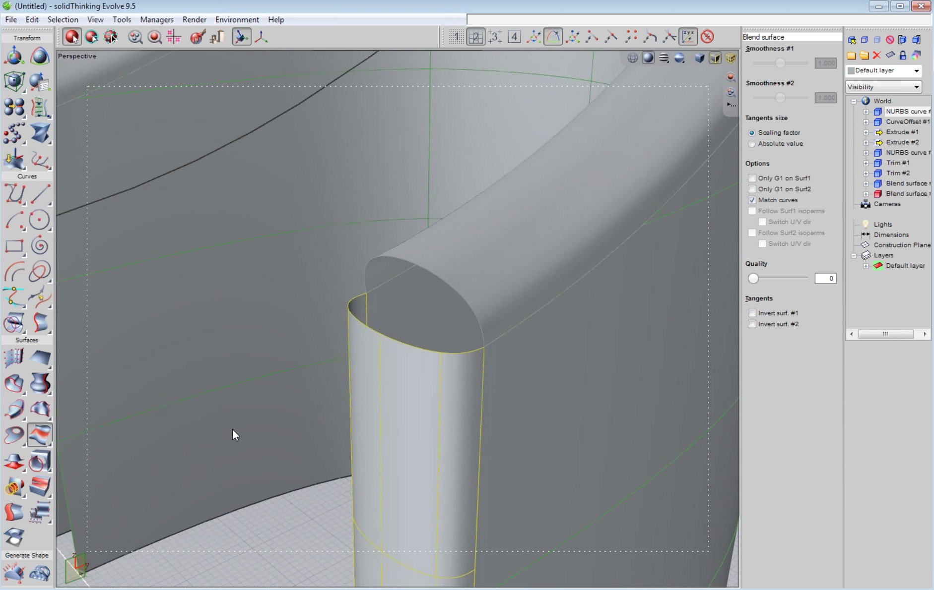
03 – Blending surfaces at awkward tangents is handled easily in solidThinking Evolve 9.5.
Blends are very important but they are not the only thing we are looking at in this chair model. The tops of the chair near the arm section is wider than other parts along that section (the original extruded width). solidThinking Evolve 9.5 allows you to highlight individual vertices one by one or select all of them on a hull (the company’s term for vertices connected in a particular row) by clicking on the hull itself. And then once selected you can manipulate the vertices like for instance scaling up or down. This was the process to giving that edge some additional width.
next page: Visual Qualities and Rendering
Visual Qualities and Rendering
solidThinking Evolve 9.5 works in a standard OpenGL view which is shaded. There are options for this as well. There are excellent lighting and shadows implemented in the typical OpenGL working view as can be seen in this bottle example from the Evolve 9.5 webinar.
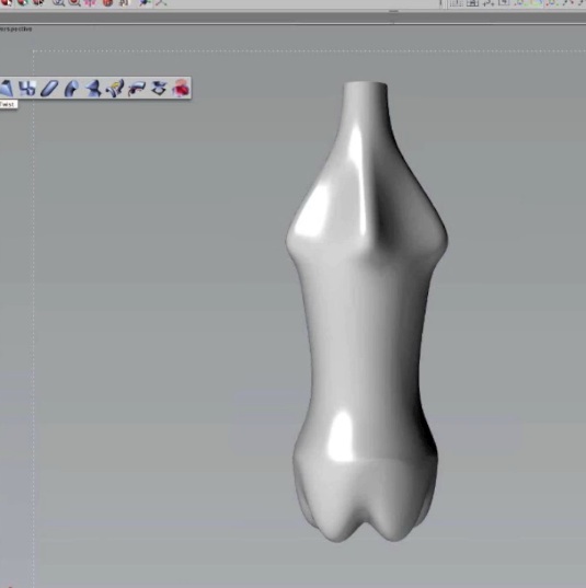
04 – The standard OpenGL rendered working window in solidThinking supports really nice shadows and lighting allowing the designer to really see and appreciate their creative work.
Adel told me during his demonstration that solidThinking Evolve’s users expect to be able to evaluate their designs, whether automobile, skateboard or armchair with real materials, lighting and put them into environments that might simulate their end use or their point of sale. For instance a showroom for a car or an environment used in a television commercial.
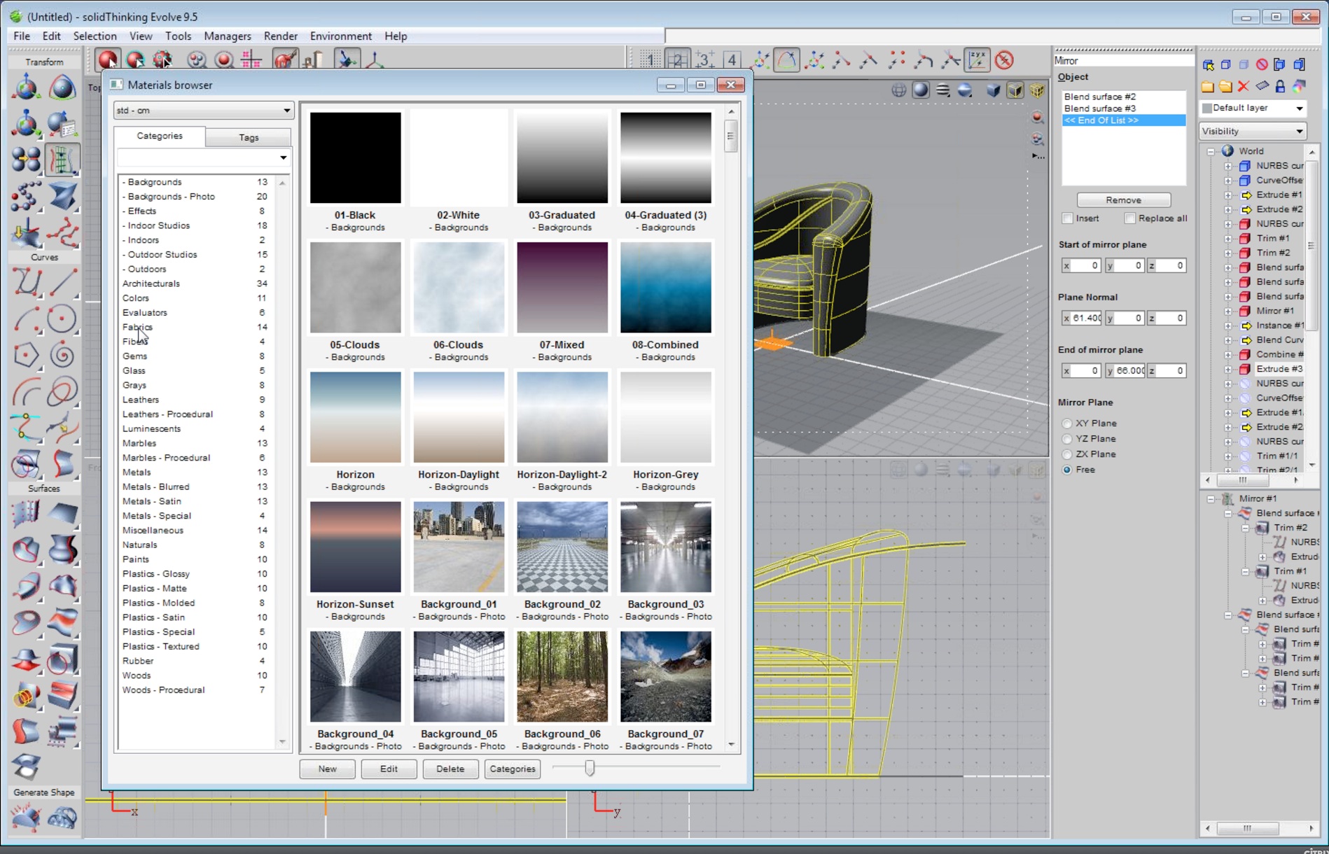
05 – solidThinking Evolve’s extensive Materials Browser helps the designer place high-quality textures and colors on designed objects for photorealistic rendering evaluations.
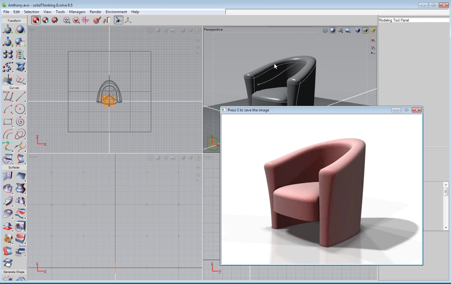
06 – You can render with photorealism within a separate viewport window.
So Evolve 9.5 features an extensive Materials Browser with hundreds of options including entire predefined sets comprising background, colors and lighting. For our armchair design for example Adel was able to pick a rose fabric quickly from the Materials Browser and render the model with its built-in photographic rendering engine. (see images 05-06)
Global Shape Controls
solidThinking has global shape controls for entire objects or subsets of areas of a model that allow you to twist, perform tapers, warps, shears and other major deformations. And it is some of these tools which suggest some of the potential use for conceptual modeling in architectural environments.
For instance, using solidThinking Evolve 9.5 it is possible to apply global shape controls to basic geometric objects–the kind that typically form the basis of buildings in urban and non-urban environments. We won’t get too deep in the architectural modeling area today in this article (more of that to come in a future article) but Adel quickly showed me how easy it was implement these global shape controls.
For instance, conceptually making a skyscraper of regular rectangular shape, Adel applied a twist function to the entire form. (see image 07 – 08).
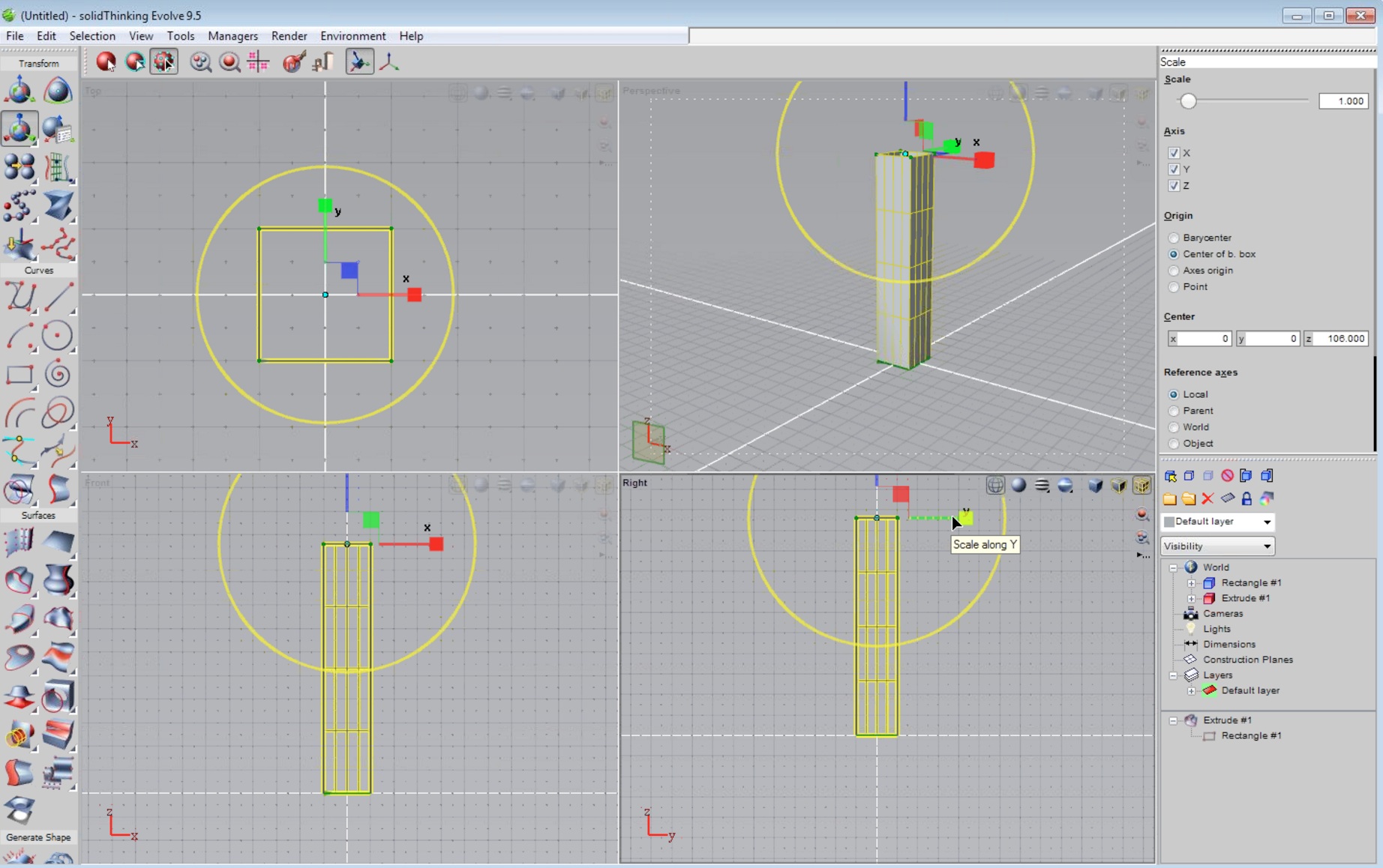
07- In this image Adel has setup a basic tower shape. The “scale” transformation is in action at the moment enabling the ability to scale up the width of the tower itself.
In the tower above it can be built up by what is called adding “sections” to the overall tallness or length of the tower form. For readers who are familiar with working with surface modelers in other programs, and in particular subdivision tools, the concept of adding addition sections is clearly familiar. For architectural CAD and modeler readers this may seem odd. To you the tower form has six sides (planes) and each of those consist of four points (vertices) constituting the corners of each plane.
In architectural tools that plane may get punctured or reshaped at its edges or added to with a bump. But subdividing it into sections is less familiar. So what we do when we subdivide the tower above into sections is prepare it for many more possibilities in global and non-global transformations.

08 – In this image we are seeing the twist function set globally to the tower form.
For example, using the twist transformation tool we can twist the entire tower from the bottom up as shown in the image above (image 08). But we might want the twist to not begin until part way up the building facade and perhaps not at its top. solidThinking Evolve 9.5 allows you to select the sections you wish the transformation tools to affect and apply the twist only to that portion. Instead of a twist you may want to do a twist and scale making the tower fatter or skinnier in particular sections. Perhaps the tower gets skinnier at the top, the way many towers actually do.
Now here is where the power of the Construction Tree comes in. You can copy this tower multiple (xN) times over within your document or place it into a new file and further iterate options as the entire Construction Tree history comes with the copy. Additionally, when you look back through your construction tree history you can go back and modify primary NURBS curves as well as primary shapes. Perhaps that tower above is switched to a five-sided pentagon plan form or perhaps a circle rather than a rectangular. You do this via the Replace function, which gives the user the ability to swap out a primary or early shape with a new one.
next page: More Power with the Round Tool
More Power with the Round Tool
Adel showed me how powerful the round tools are in solidThinking. This comes into play with industrial shapes rather than architecture but you could easily imagine possible uses with buildings as well. Starting with just a regular cube (image 09) Adel transformed the edges into rounded edges with a particular radius. Now focus on the resolution of the corners. (see image 10). The various round tool controls give you options like sew tolerance, default radius, shape controls that include chamfer, smooth corners, smooth variable radius, smooth Y blends, setback corners and collars on setbacks. There are also overlap controls. (see right side of image 10).
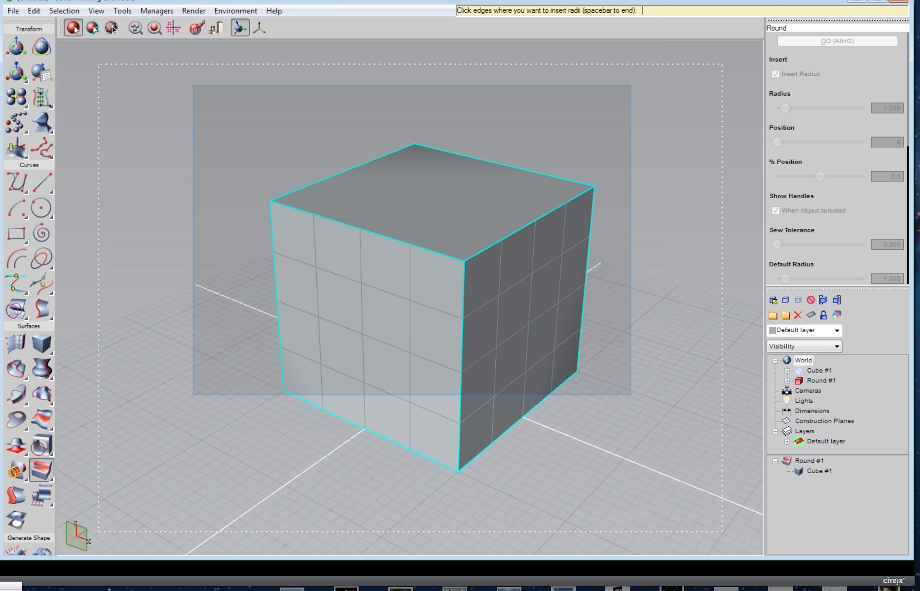
09 – A basic shape can be altered substantially using just simple but powerful tools like the round tool.
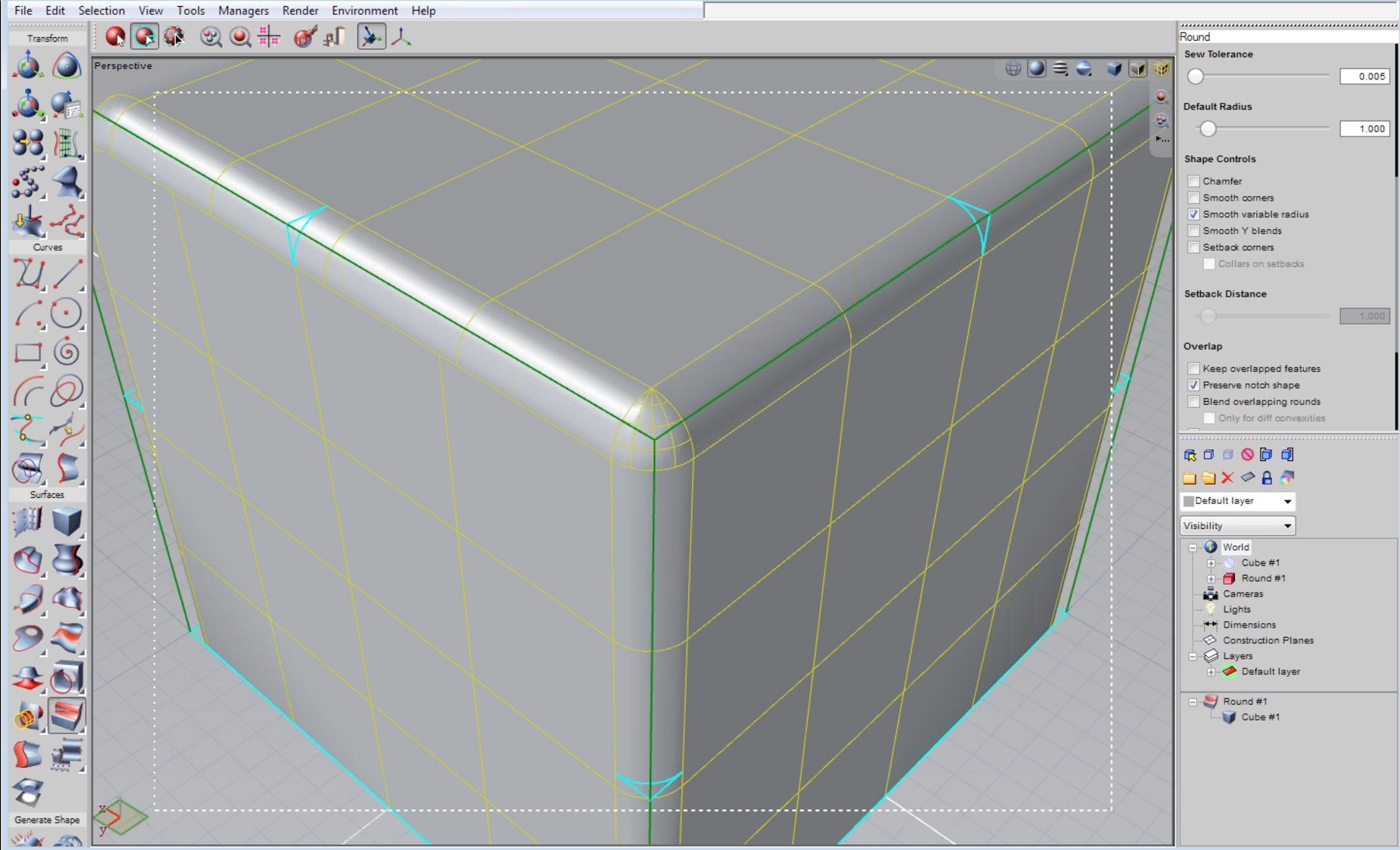
10 – The round tool has been applied to the edges of this cube. Difference radii can be applied to each edge.
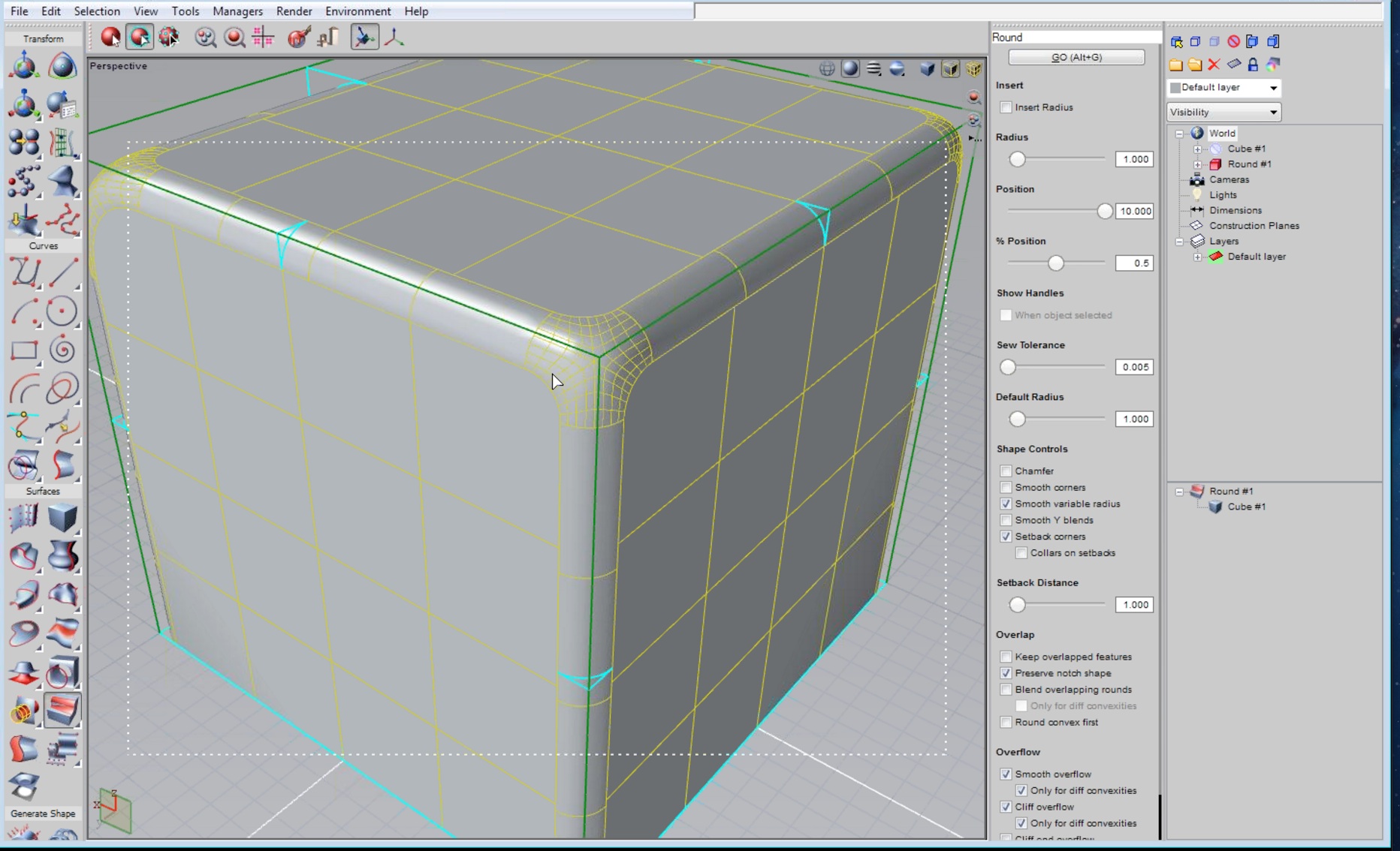
11 – Intersections with radii can be handled many different ways. Setback corners have been applied here.
In the third image above (image 11) setback corners was chosen and the results are different than in image 10. In the next image Adel showed me how solidThinking can handle a variable radius along one side of the cube and how the other faces resolve smoothly. (see image 12). This was quite satisfying to watch in action as the surfaces handle the transformations so gracefully. Remember, this is all NURBS still.
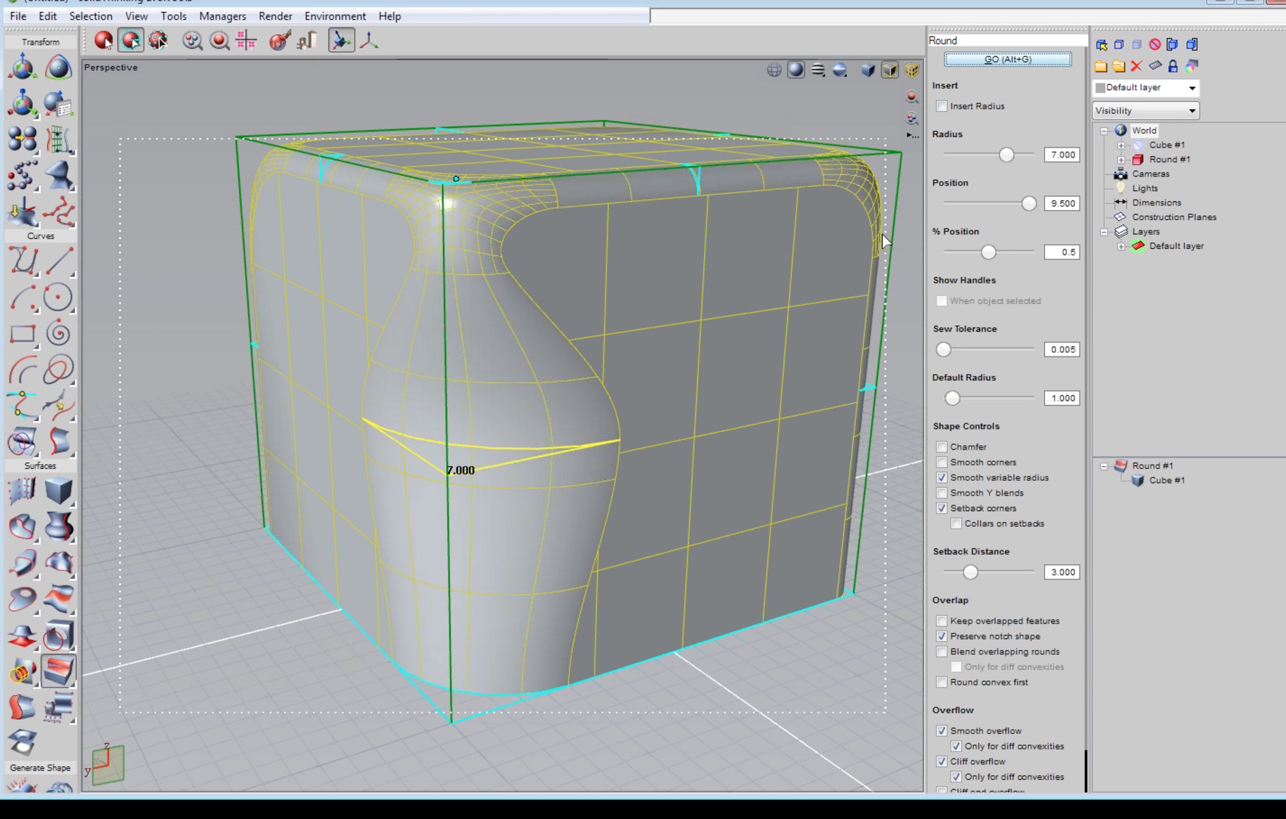
12 – Different radii can be applied to sections of an edge to produce results such as this. Basic transformations to edges even this way can create sophisticated shapes from basic geometry.
As Adel said, even with a simple shape, with the radius tools in solidThinking you can create really very nice and complicated forms.
Closing Thoughts
There is a lot more we can go over in solidThinking Evolve 9.5. In this the first of a few special articles on solidThinking and we wanted to cover some of the basics of the program’s modeling prowess.
solidThinking includes a dynamic high-quality rendering feature that enables the designer to visualize and design at the same time. You can be in a pure modeling mode and then get curious about lighting and shadows on your product or building and quickly generate a high-quality render to evaluate your design. The interactive rendering window floats over your primary interface windows so you can position a photorealistic view to the side while you continue to iterate your model. (see image 13).
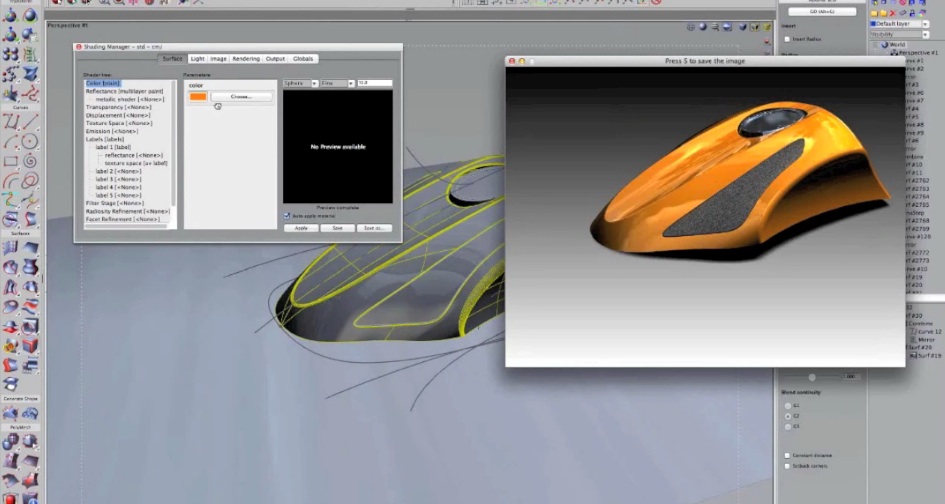
13 – Interactive render mode puts a photorealistic render viewport above the work area.
As we said at the beginning of this article solidThinking’s parent company Altair Corporation was at AIA. There’s a new story altogether evolving in that direction that deserves fuller attention. But as we approach the Fall we will continue to focus on solidThinking Evolve and Inspire specifically so that readers can fully see and understand what these programs are all about. To learn more go to solidThinking directly on the web. They have a lot of instructional videos that show you quite a bit.