Continued from page 1
Part 2: Sample Problems and Workflow
One of the most important concepts in solidThinking Inspire is the concept of the “design space.” This is the three dimensional volume form or space in which mass optimization takes place. (see image 03). An individual volume is assigned as the “design space” and this turns that volume a reddish brown. When optimizations are run on this design space, after loads and supports are set in place, Inspire 2014 produces an optimized mass for that part or section of a part assembly. (see image 04).
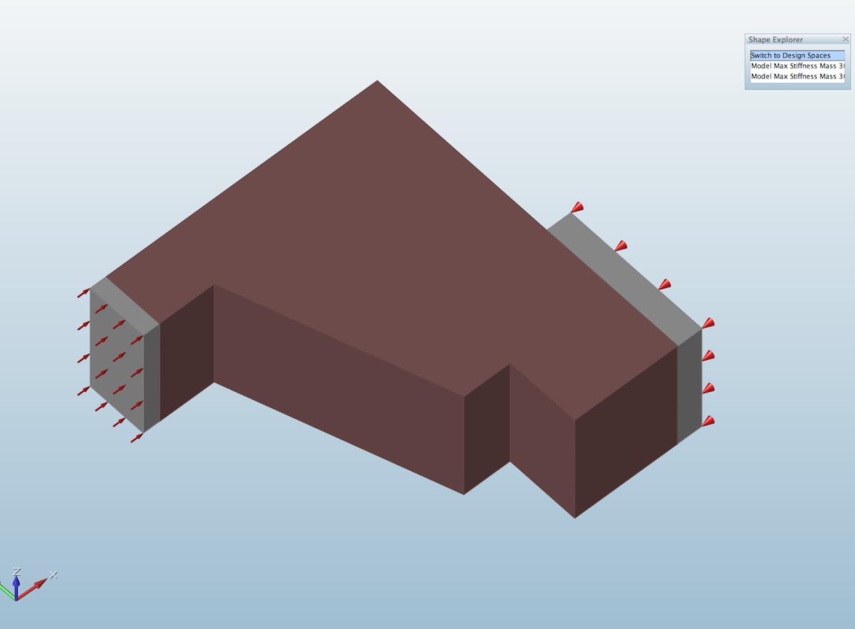
03 – In Inspire 2014 you establish the “design space”, the volume from which mass optimization takes place.
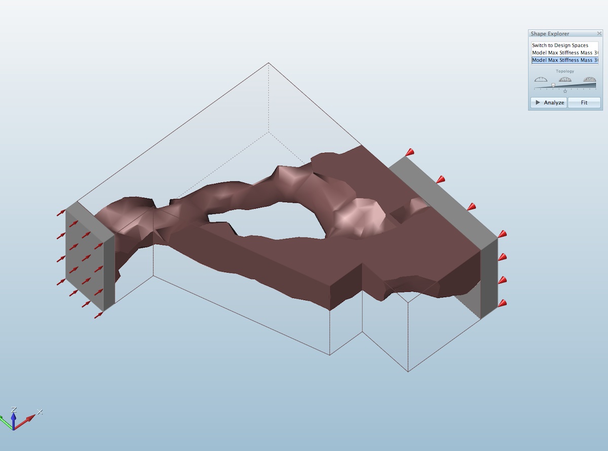
04 – The design space is now shown in outline with the “optimized mass” part remaining.
The design space is the volume from which mass optimizations occur but analysis takes place across the entire assembly of model connected to the design space. In terms of how one works in the program, generally, between operations one hits the escape key or right clicks on the mouse to exist specific tools and procedures in order to then choose new tools and procedures. The video below shows the the nature of creating a “design space” as well as demonstrate the push/pull modeling tools.
The video above shows how quick it is to create a “design space” with a basic shape. We learned during the review that the simpler you can make the design space the faster optimizations would run. This makes sense, naturally, but was not obvious at first.
One thing that is very important to note about Inspire 2014 is that design spaces should be not very complicated, they should be simple volumes. The more complicated a design space is the more time it takes to run an optimization process. This is very important because Inspire doesn’t support the ability to work on more than one model at a time. So while optimizations run in the background, you can’t load another model in the foreground and work on it as another optimization runs in the background.
A Beam Problem: Design Spaces, Analysis and Optimization
A more complete sample problem is really in order here but this time we’ll cast the problem in basic architectural terms and conceptually study a simple beam. We realize folks are not interested in Inspire so they can design beams, and even if you were this is not the program for that. However, a beam is a basic structural concept architects will understand. Additionally, architects will also be looking for a result that meets the expectations of their training.
The beam volume is established as the “design space” (shown in reddish brown). It sits on columns, which are not part of the design space, and supports are positioned at the base of these columns. Prior to optimization, a quick analysis test was run and results are shown in the images below (04 – 06). As you also see displacement maxes out at the beam’s top edge as the supports are at the column bases. If the columns were shorter—and therefore closer to the design space carrying the loads—the displacement would be smaller.
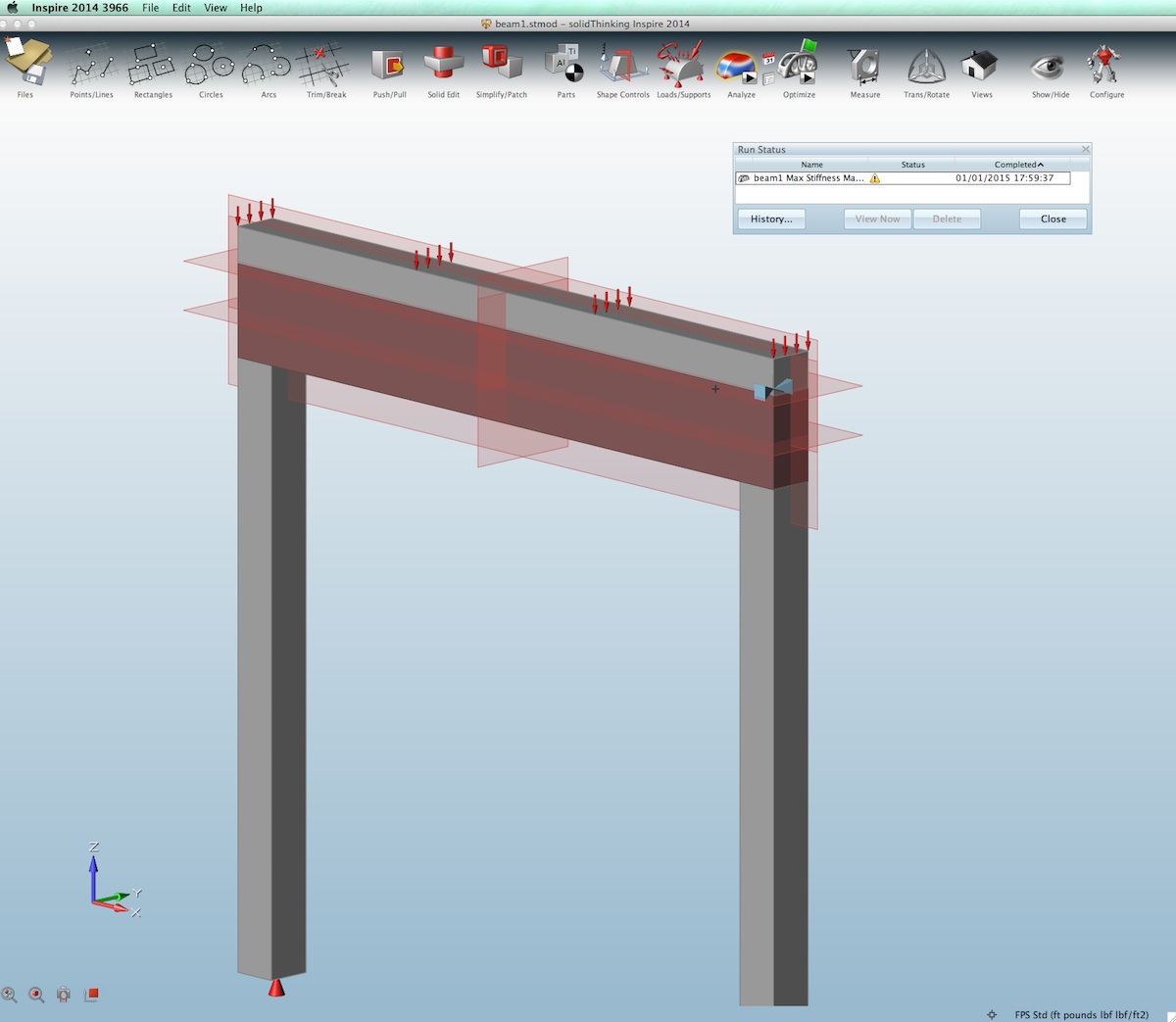
05 – basic beam problem defined with beam volume as “design space”
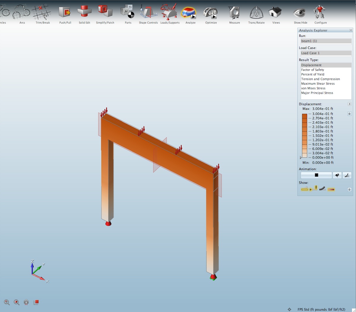
06 – in this analysis of the design space without optimization we see the displacement.
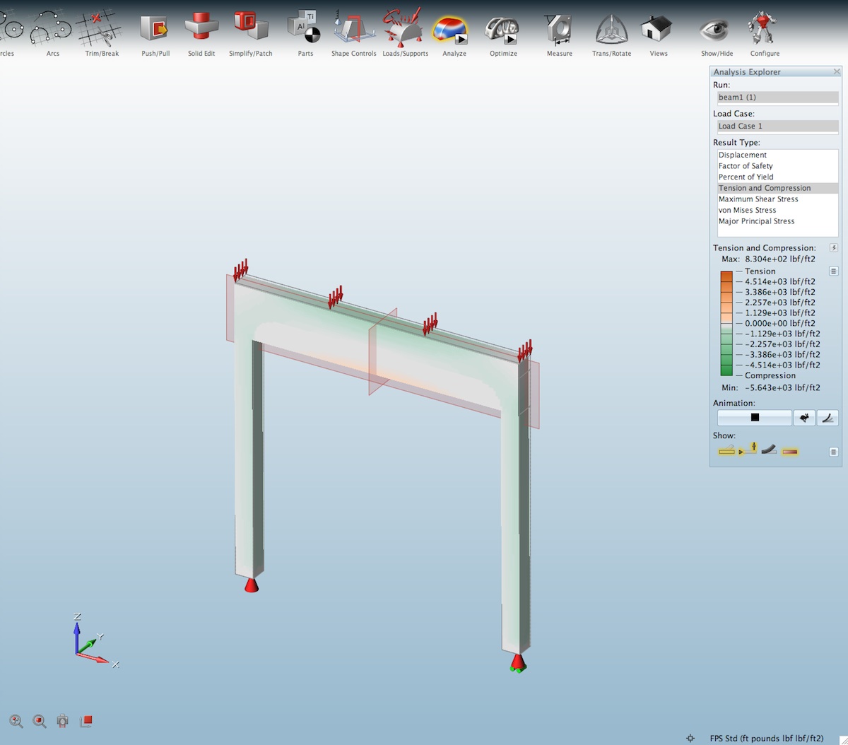
07 – beam analysis, compression and tension.
One reason we start with a beam is because architects understand how such structural members respond to loads. An even distributed load is going to cause a maximum deflection of the beam at its center. Unsupported laterally, we can also examine how the stresses (forces) move the structure as a “design space” and this should intuit in the architect or industrial designer what ways the structural package can be developed to resist the forces applied to it, as well as what is likely necessary in the surrounding elements about the design space. (see image 05 for displacement, which runs perpendicular to the beam’s length).
Next we run the mass optimization. In both the running of analysis and optimization we hit the “play” button on the icon in the toolbar. (see image 08)
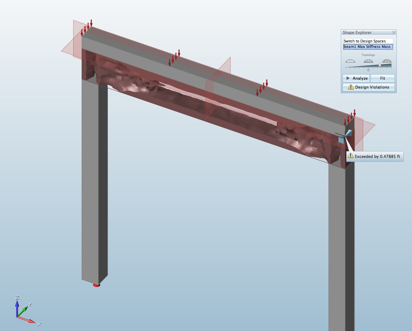
08 – Beam problem, mass optimization view showing the “design space” now minimized to the location of mass what is needed to resist forces (loads) on design space.
Our mass target was the default 30 percent of the design space. A slider presents itself in the Shape Explorer palette, with icons that indicate minimum and maximum mass targets. You can also toggle back and forth between the optimized mass view and the design space itself. (see image 08 above). In the view above we slid the mass slider up towards more mass in order to connect all masses with the design space volume. This is critical for analysis runs on the optimized mass, which is what you do next by hitting the Analyze button in the Shape Explorer. (see image 08 above and result in image 09 below).
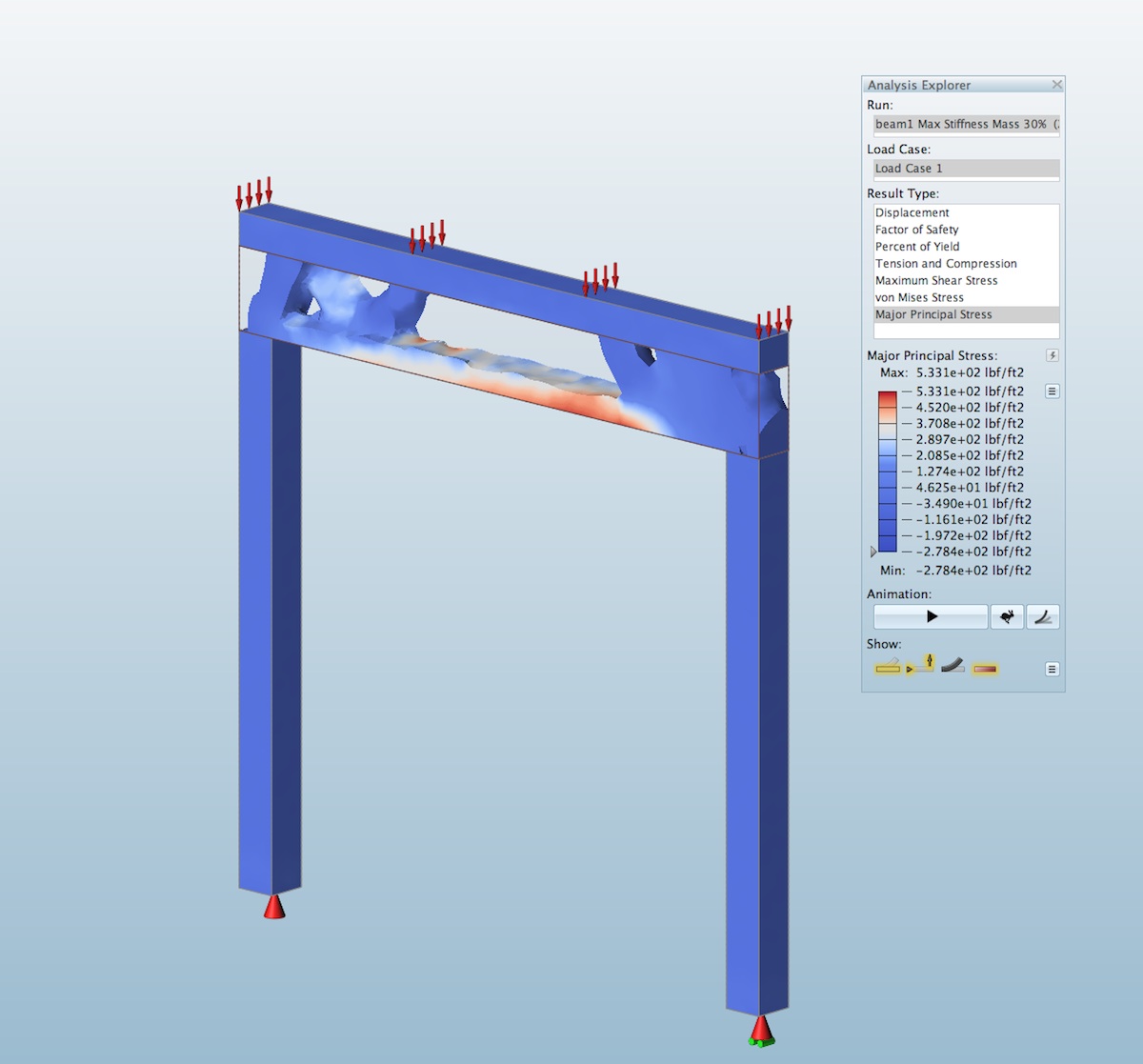
09 – the beam’s optimized mass is now show under analysis, showing max. stress in this view.
A few things to point out. If you were expecting a wide-flange beam shape clearly we don’t quite have that. But it’s not far off. What is in affect happening above is that the load block (in grey) is acting like the top flange and the mass between (top and bottom) is thinned out, particularly at its center. As you can see above, architects already know that the top of the beam is in maximum compression while the bottom center section is in maximum tension, indicated in red in the analyze view (image 09). Directly in the middle there is zero tension or compression at a particular point, in other words zero forces. This partly explains why there is air in the direct middle—mass is not needed there because no forces transfer through that section and hence you don’t need mass. In real steel beams, of course, we have a consistent web across the main body of the beam for manufacturing reasons.
Let’s move on to more fun activities in Inspire 2014 by exploring quickly, some architectural forms and some of the visualization aspects of the program that make this tool really interesting to work with.
next page: Part 3: Introduction to Architectural Exploration with Inspire 2014

Reader Comments
Mike Laney liked this on Facebook.
Matthew Ivanov liked this on Facebook.
Mike Laney liked this on Facebook.
Matthew Ivanov liked this on Facebook.
In this product review, Architosh looks at the unique solidThinking Inspire 2014 CAE-based industrial design and arc…https://t.co/5hoRdBJ7F0
In this product review, Architosh looks at the unique solidThinking Inspire 2014 CAE-based industrial design and arc…https://t.co/5hoRdBJ7F0
http://t.co/GFQFQ7SMgi — can solidThinking Inspire 2014 add innovation to architectural professionals? Read on! http://t.co/OXUG0ddBhF
http://t.co/GFQFQ7SMgi — can solidThinking Inspire 2014 add innovation to architectural professionals? Read on! http://t.co/OXUG0ddBhF
@solidThinking Inspire 2014 http://t.co/o9yTXhmUWh by Anthony Frausto-Robledo #mcad #cad
@solidThinking Inspire 2014 http://t.co/o9yTXhmUWh by Anthony Frausto-Robledo #mcad #cad
Check out @architosh review of Inspire for the Architectural market. http://t.co/USw0KTZC7v #architecture, #design, #software
Check out @architosh review of Inspire for the Architectural market. http://t.co/USw0KTZC7v #architecture, #design, #software
Comments are closed.